Nissan Frontier. Instruction - part 714
TIMING CHAIN
EM-45
< REMOVAL AND INSTALLATION >
[QR25DE]
C
D
E
F
G
H
I
J
K
L
M
A
EM
N
P
O
TIMING CHAIN
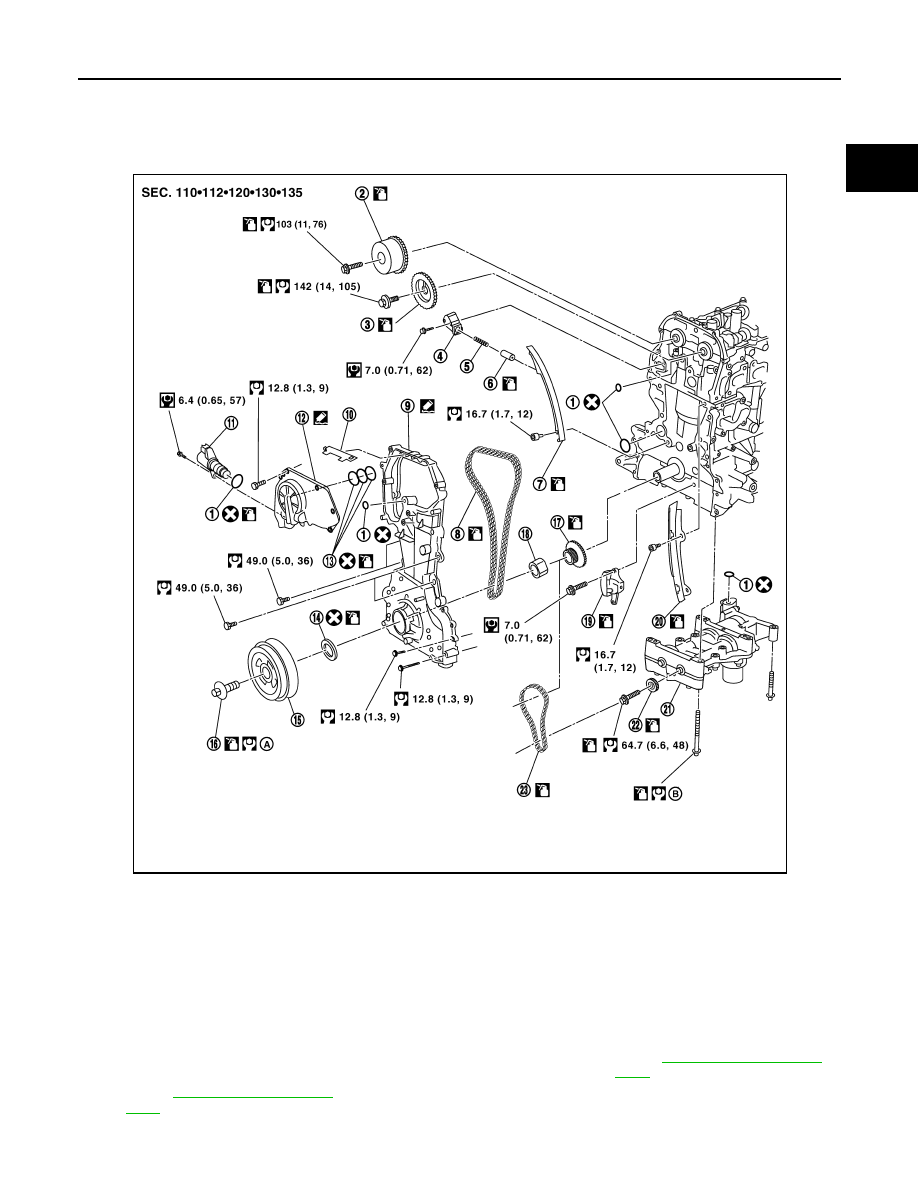
Exploded View
INFOID:0000000009478064
1.
O-ring
2.
Camshaft sprocket (INT)
3.
Camshaft sprocket (EXH)
4.
Chain tensioner
5.
Spring
6.
Chain tensioner plunger
7.
Timing chain slack guide
8.
Timing chain
9.
Front cover
10. Chain guide
11.
Intake valve timing control solenoid
valve
12. Intake valve timing control cover
13. Oil ring
14. Front oil seal
15. Crankshaft pulley
16. Crankshaft pulley bolt
17. Crankshaft sprocket
18. Spacer
19. Balancer unit timing chain tensioner
20. Timing chain tension guide
21. Balancer unit
22. Balancer unit sprocket
23. Balancer unit timing chain
A.
B.
WBIA0834E