Nissan Frontier. Instruction - part 704


  Index      Nissan     Nissan Frontier (2014 year) - Service and Repair Instruction


Search            copyright infringement  


Content   ..  702  703  704  705   ..


Nissan Frontier. Instruction - part 704


PRECAUTIONS

EM-5

< PRECAUTION >

[QR25DE]

C

D

E

F

G

H

I

J

K

L

M

A

EM

N

P

O

Precaution for Assembly and Installation

INFOID:0000000009478032

• Use torque wrench to tighten bolts or nuts to specification.

• When tightening nuts and bolts, as a basic rule, equally tighten in several different steps starting with the

ones in center, then ones on inside and outside diagonally in this order. If the order of tightening is specified,

do exactly as specified.

• Replace with new gasket, packing, oil seal or O-ring.

• Thoroughly wash, clean, and air-blow each part. Carefully check engine oil or engine coolant passages for

any restriction and blockage. 

• Avoid damaging sliding or mating surfaces. Completely remove foreign materials such as cloth lint or dust.

Before assembly, oil sliding surfaces well. 

• Release air within route when refilling after draining engine coolant. 

• Before starting engine, apply fuel pressure to fuel lines with turning ignition switch ON (with engine stopped).

Then make sure that there are no leaks at fuel line connections.

• After repairing, start engine and increase engine speed to check engine coolant, fuel, engine oil, and

exhaust gasses for leakage.

Parts Requiring Angle Tightening

INFOID:0000000009478033

• For the final tightening of the following engine parts use Tool: 

- Cylinder head bolts

- Lower cylinder block bolts

- Connecting rod cap bolts

- Crankshaft pulley bolt (No angle wrench is required as bolt flange is provided with notches for angle tighten-

ing)

• Do not use a torque value for final tightening. 

• The torque value for these parts are for a preliminary step.

• Ensure thread and seat surfaces are clean and coated with engine oil. 

Precaution for Liquid Gasket

INFOID:0000000009478034

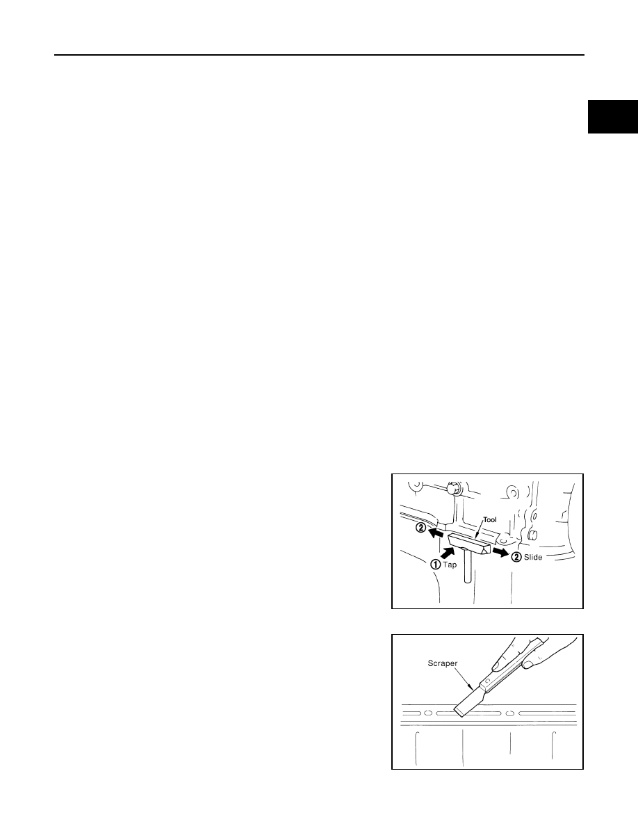
REMOVAL OF LIQUID GASKET 

• After removing the bolts and nuts, separate the mating surface and

remove the old liquid gasket using Tool.

CAUTION:

Do not damage the mating surfaces.

• Tap the seal cutter to insert it (1).

• In areas where the Tool is difficult to use, lightly tap to slide it (2).

LIQUID GASKET APPLICATION PROCEDURE

1. Remove the old liquid gasket adhering to the gasket application

surface and the mating surface using suitable tool.

• Remove the liquid gasket completely from the groove of the

liquid gasket application surface, bolts, and bolt holes.

2. Thoroughly clean the mating surfaces and remove adhering

moisture, grease and foreign material.

Tool number

: KV10112100 (BT-8653-A)

Tool number

: KV10111100 (J-37228)

WBIA0566E

PBIC0003E

EM-6

< PRECAUTION >

[QR25DE]

PRECAUTIONS

3. Attach the liquid gasket tube to the Tool.

Use Genuine RTV Silicone Sealant or equivalent. Refer to

GI-21, "Recommended Chemical Products and Sealants"

4. Apply the liquid gasket without breaks to the specified location

with the specified dimensions.

• If there is a groove for the liquid gasket application, apply the

liquid gasket to the groove.

• Normally apply the liquid gasket on the inside edge of the bolt

holes. Also apply to the outside edge of the bolt holes when

specified in the procedure.

• Within five minutes of liquid gasket application, install the mat-

ing component.

• If the liquid gasket protrudes, wipe it off immediately.

• Do not retighten after the installation.

• Wait 30 minutes or more after installation before refilling the

engine with oil or coolant.

CAUTION:

If there are more specific instructions in the procedures contained in this instruction concerning liq-

uid gasket application, observe them.

Tool number

: WS39930000 ( — )

WBIA0567E

SEM159F

PREPARATION

EM-7

< PREPARATION >

[QR25DE]

C

D

E

F

G

H

I

J

K

L

M

A

EM

N

P

O

PREPARATION

PREPARATION

Special Service Tool

INFOID:0000000009478035

The actual shape of the tools may differ from those illustrated here.

Tool number
(TechMate No.)
Tool name

Description

KV10111100
(J-37228)
Seal cutter

Removing oil pan and front cover, etc.

KV10116200
(J-26336-A)
Valve spring compressor
1. KV10115900
(J-26336-20)
Attachment
2. KV10109220
( — )
Adapter

Disassembling valve mechanism
Part (1) is a component of KV10116200 (J-
26336-A), but Part (2) is not so.

KV10112100
(BT-8653-A)
Angle wrench

Tightening bolts for cylinder head, main bear-
ing cap and connecting rod cap

KV10117100
(J-36471-A)
Heated oxygen sensor wrench

Loosening or tightening air fuel ratio sensor 1
For 22 mm (0.87 in) width hexagon nut

KV10107902
(J-38959)
Valve oil seal puller

Replacing valve oil seal

KV10115600
(J-38958)
Valve oil seal drift

Installing valve oil seal

S-NT046

PBIC1650E

AWBIA1043ZZ

NT379

NT011

NT024

EM-8

< PREPARATION >

[QR25DE]

PREPARATION

EM03470000
(J-8037)
Piston ring compressor

Installing piston assembly into cylinder bore

ST16610001
(J-23907)
Pilot bushing puller

Removing pilot bushing (M/T models) or pilot 
converter (A/T models)

WS39930000
( — )
Tube presser

Pressing the tube of liquid gasket

16441 6N210    
(J-45488)
Quick connector release

Removing fuel tube quick connectors in en-
gine room.

(J-46535)
Drive belt tension releaser

Releasing drive belt tension

KV991J0050
(J-44626)
Air fuel sensor Socket

Loosening or tightening air fuel ratio A/F sen-
sor
a: 22 mm (0.87 in)

Tool number
(TechMate No.)
Tool name

Description

NT044

NT045

NT052

PBIC0198E

WBIA0536E

LBIA0444E


Content   ..  702  703  704  705   ..