Nissan Frontier. Instruction - part 696
IGNITION SIGNAL
EC-1355
< DTC/CIRCUIT DIAGNOSIS >
[VQ40DE FOR MEXICO]
C
D
E
F
G
H
I
J
K
L
M
A
EC
N
P
O
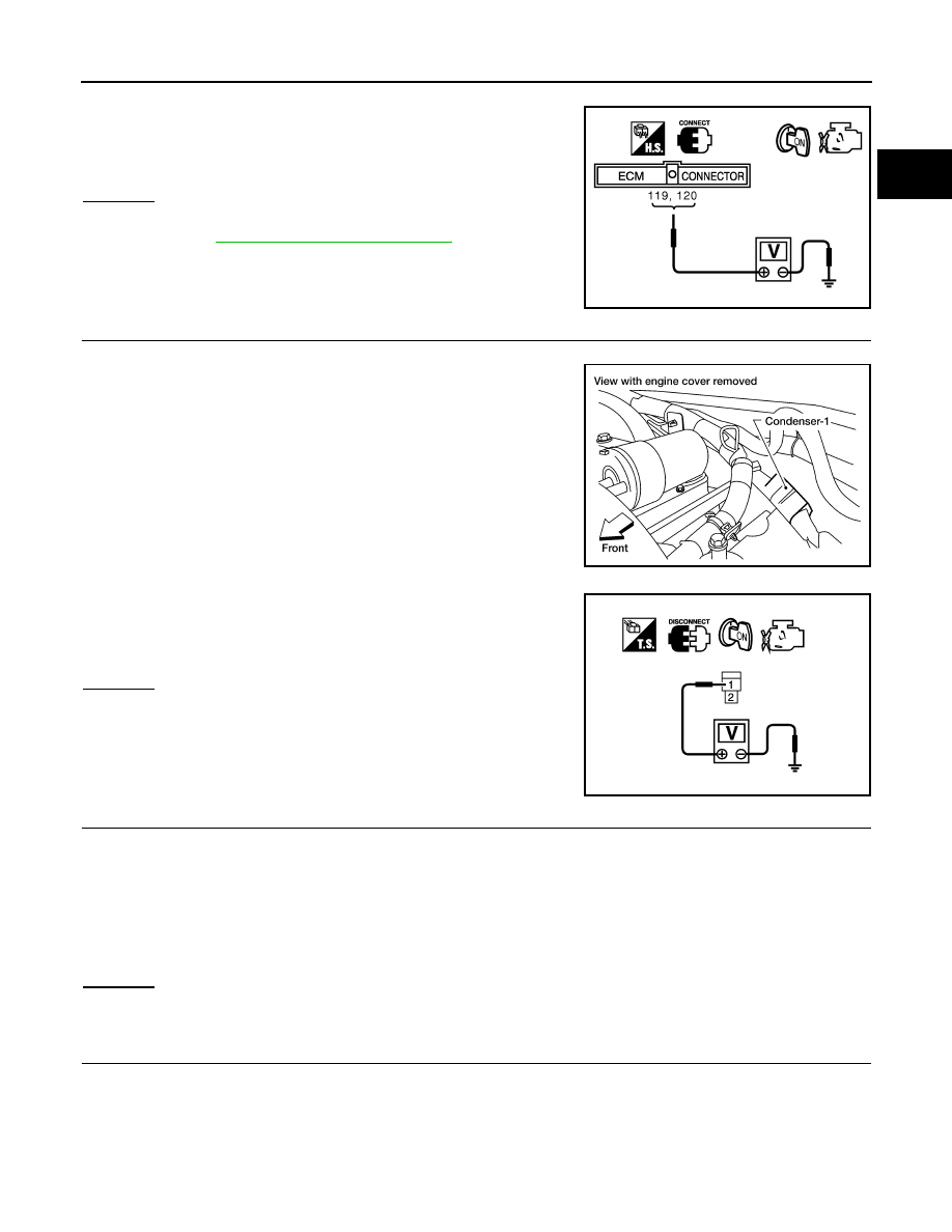
1. Turn ignition switch OFF, wait at least 10 seconds and then turn it ON.
2. Check voltage between ECM terminals 119, 120 and ground
with CONSULT or tester.
OK or NG
OK
>> GO TO 5.
NG
>> Go to
EC-1091, "Diagnosis Procedure"
5.
CHECK IGNITION COIL POWER SUPPLY CIRCUIT-II
1. Turn ignition switch OFF.
2. Disconnect condenser-1 harness connector.
3. Turn ignition switch ON.
4. Check voltage between condenser-1 terminal 1 and ground with
CONSULT or tester.
OK or NG
OK
>> GO TO 8.
NG
>> GO TO 6.
6.
CHECK IGNITION COIL POWER SUPPLY CIRCUIT-III
1. Turn ignition switch OFF.
2. Disconnect IPDM E/R harness connector E119.
3. Check harness continuity between IPDM E/R terminal 3 and condenser-1 terminal 1.
Refer to Wiring Diagram.
4. Also check harness for short to ground and short to power.
OK or NG
OK
>> GO TO 17.
NG
>> GO TO 7.
7.
DETECT MALFUNCTIONING PART
Check the following.
• Harness connectors E2, F32
• Harness for open or short between condenser-1 and IPDM E/R
>> Repair open circuit or short to ground or short to power in harness or connectors.
Voltage: Battery voltage
MBIB0034E
BBIA0562E
Voltage: Battery voltage
PBIB0624E
Continuity should exist.