Nissan Frontier. Instruction - part 658


  Index      Nissan     Nissan Frontier (2014 year) - Service and Repair Instruction


Search            copyright infringement  


Content   ..  656  657  658  659   ..


Nissan Frontier. Instruction - part 658


P0340, P0345 CMP SENSOR (PHASE)

EC-1203

< DTC/CIRCUIT DIAGNOSIS >

[VQ40DE FOR MEXICO]

C

D

E

F

G

H

I

J

K

L

M

A

EC

N

P

O

>> INSPECTION END

Component Inspection

INFOID:0000000009481849

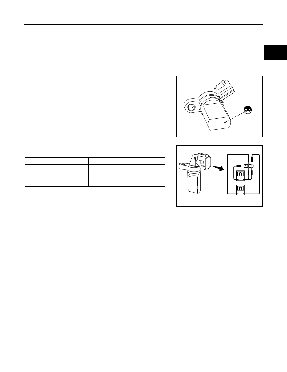
CAMSHAFT POSITION SENSOR (PHASE)

1. Loosen the fixing bolt of the sensor.
2. Disconnect camshaft position sensor (PHASE) harness connector.
3. Remove the sensor.
4. Visually check the sensor for chipping.

5. Check resistance as shown in the figure.

PBIB0563E

Terminal No. (Polarity)

Resistance 

Ω [at 25°C (77°F)]

1 (+) - 2 (-)

Except 0 or 

1 (+) - 3 (-)

2 (+) - 3 (-)

PBIB0564E

EC-1204

< DTC/CIRCUIT DIAGNOSIS >

[VQ40DE FOR MEXICO]

P0420, P0430 THREE WAY CATALYST FUNCTION

P0420, P0430 THREE WAY CATALYST FUNCTION

On Board Diagnosis Logic

INFOID:0000000009481850

The ECM monitors the switching frequency ratio of air fuel ratio (A/F)

sensor 1 and heated oxygen sensor 2.

A three way catalyst (manifold) with high oxygen storage capacity

will indicate a low switching frequency of heated oxygen sensor 2.

As oxygen storage capacity decreases, the heated oxygen sensor 2

switching frequency will increase.

When the frequency ratio of air fuel ratio (A/F) sensor 1 and heated

oxygen sensor 2 approaches a specified limit value, the three way

catalyst (manifold) malfunction is diagnosed.

DTC Confirmation Procedure

INFOID:0000000009481851

NOTE:

If DTC Confirmation Procedure has been previously conducted, always perform the following before conduct-

ing the next step.

1. Turn ignition switch OFF and wait at least 10 seconds.

2. Turn ignition switch ON.

3. Turn ignition switch OFF and wait at least 10 seconds.

 WITH CONSULT

TESTING CONDITION:

Do not maintain engine speed for more than the specified minutes below.
1. Turn ignition switch ON and select “DATA MONITOR” mode with CONSULT.
2. Start engine and warm it up to the normal operating temperature.
3. Turn ignition switch OFF and wait at least 10 seconds.
4. Turn ignition switch ON.
5. Turn ignition switch OFF and wait at least 10 seconds.
6. Start engine and keep the engine speed between 3,500 and 4,000 rpm for at least 1 minute under no load.
7. Let engine idle for 1 minute.
8. Check that “COOLAN TEMP/S” indicates more than 70

°C (158°F).

If not, warm up engine and go to next step when “COOLAN TEMP/S” indication reaches to 70

°C (158°F).

9. Open engine hood.
10. Select “DTC & SRT CONFIRMATION” then “SRT WORK SUPPORT” mode with CONSULT.
11. Rev engine between 2,000 and 3,000 rpm and hold it for 3 consecutive minutes then release the acceler-

ator pedal completely.

If “INCMP” of “CATALYST” changed to “CMPLT”, go to step 12.

12. Wait 5 seconds at idle.
13. Rev engine between 2,000 and 3,000 rpm and maintain it until “INCMP” of “CATALYST” changes to

“CMPLT” (It will take approximately 5 minutes).

If not “CMPLT”, stop engine and cool it down to less than 70

°C (158°F) and then retest from step 1.

14. Select “SELF-DIAG RESULTS” mode with CONSULT.

PBIB2377E

DTC No.

Trouble diagnosis name

DTC detecting condition

Possible cause

P0420
0420
(Bank 1)

Catalyst system efficien-
cy below threshold

• Three way catalyst (manifold) does not oper-

ate properly.

• Three way catalyst (manifold) does not have 

enough oxygen storage capacity.

• Three way catalyst (manifold)
• Exhaust tube
• Intake air leaks
• Fuel injector
• Fuel injector leaks
• Spark plug
• Improper ignition timing

P0430
0430
(Bank 2)

P0420, P0430 THREE WAY CATALYST FUNCTION

EC-1205

< DTC/CIRCUIT DIAGNOSIS >

[VQ40DE FOR MEXICO]

C

D

E

F

G

H

I

J

K

L

M

A

EC

N

P

O

15. Confirm that the 1st trip DTC is not detected.

If the 1st trip DTC is detected, go to 

EC-1205, "Diagnosis Procedure"

.

Overall Function Check

INFOID:0000000009481852

Use this procedure to check the overall function of the three way catalyst (manifold). During this check, a 1st

trip DTC might not be confirmed.

 WITH GST

1. Start engine and warm it up to the normal operating temperature.
2. Turn ignition switch OFF and wait at least 10 seconds.
3. Turn ignition switch ON.
4. Turn ignition switch OFF and wait at least 10 seconds.
5. Start engine and keep the engine speed between 3,500 and 4,000 rpm for at least 1 minute under no load.
6. Let engine idle for 1 minute.
7. Open engine hood.
8. Set voltmeter probe between ECM terminals 74 [HO2S2 (bank

1) signal], 55 [HO2S2 (bank 2) signal] and ground.

9. Keep engine speed at 2,500 rpm constant under no load.
10. Check that the voltage does not vary for more than 5 seconds.

If the voltage fluctuation cycle takes less than 5 seconds, go to

EC-1205, "Diagnosis Procedure"

.

• 1 cycle: 0.6 - 1.0 

→ 0 - 0.3 → 0.6 - 1.0

Diagnosis Procedure

INFOID:0000000009481853

1.

CHECK EXHAUST SYSTEM

Visually check exhaust tubes and muffler for dents.
OK or NG

OK

>> GO TO 2.

NG

>> Repair or replace.

2.

CHECK EXHAUST GAS LEAK

1. Start engine and run it at idle.

2. Listen for an exhaust gas leak before the three way catalyst (manifold).

OK or NG

OK

>> GO TO 3.

NG

>> Repair or replace.

3.

CHECK INTAKE AIR LEAK

Listen for an intake air leak after the mass air flow sensor.
OK or NG

OK

>> GO TO 4.

PBIB1108E

PBIB1216E

EC-1206

< DTC/CIRCUIT DIAGNOSIS >

[VQ40DE FOR MEXICO]

P0420, P0430 THREE WAY CATALYST FUNCTION

NG

>> Repair or replace.

4.

CHECK IGNITION TIMING

Check the following items. Refer to 

EC-1068, "Basic Inspection"

.

OK or NG

OK

>> GO TO 5.

NG

>> Follow the 

EC-1068, "Basic Inspection"

.

5.

CHECK FUEL INJECTOR

1. Stop engine and then turn ignition switch ON.

2. Check voltage between ECM terminals 21, 22, 23, 40, 41, 42

and ground with CONSULT or tester.

Refer to Wiring Diagram for FUEL INJECTOR, 

EC-1043, "Wiring

Diagram"

.

OK or NG

OK

>> GO TO 6.

NG

>> Perform 

EC-1346, "Diagnosis Procedure"

.

6.

CHECK FUNCTION OF IGNITION COIL-I

CAUTION:

perform the following procedure in a place with no combustible objects and good ventilation.

1. Turn ignition switch OFF.

2. Remove fuel pump fuse (No.48) in IPDM E/R to release fuel

pressure.

NOTE:

Do not use CONSULT to release fuel pressure, or fuel pressure

applies again during the following procedure.

3. Start engine.

4. After engine stalls, crank it two or three times to release all fuel

pressure.

5. Turn ignition switch OFF.

6. Remove all ignition coil harness connectors to avoid the electri-

cal discharge from the ignition coils.

7. Remove ignition coil and spark plug of the cylinder to be

checked.

8. Crank engine for five seconds or more to remove combustion gas in the cylinder.

9. Connect spark plug and harness connector to ignition coil.

10. Fix ignition coil using a rope etc. with gap of 13 - 17 mm (0.52 -

0.66 in) between the edge of the spark plug and grounded metal

portion as shown in the figure.

11. Crank engine for about three seconds, and check whether spark

is generated between the spark plug and the grounded metal

portion.

CAUTION:

• Never place to the spark plug and the ignition coil within

50 cm (19.7 in)each other. Be careful not to get an electri-

cal shock while checking, because the electrical dis-

charge voltage becomes 20 kV or more.

Items

Specifications

Target idle speed

625 

± 50 rpm (in P or N position)

Ignition timing

15 

± 5° BTDC (in P or N position)

Battery voltage should exist.

PBIB1172E

Spark should be generated.

BBIA0534E

JMBIA0066GB


Content   ..  656  657  658  659   ..