Nissan Frontier. Instruction - part 553
P0451 EVAP CONTROL SYSTEM PRESSURE SENSOR
EC-783
< DTC/CIRCUIT DIAGNOSIS >
[VQ40DE FOR USA AND CANADA]
C
D
E
F
G
H
I
J
K
L
M
A
EC
N
P
O
OK
>> GO TO 2.
NG
>> Repair or replace ground connections.
2.
CHECK EVPA CONTROL SYSTEM PRESSURE SENSOR CONNECTOR FOR WATER
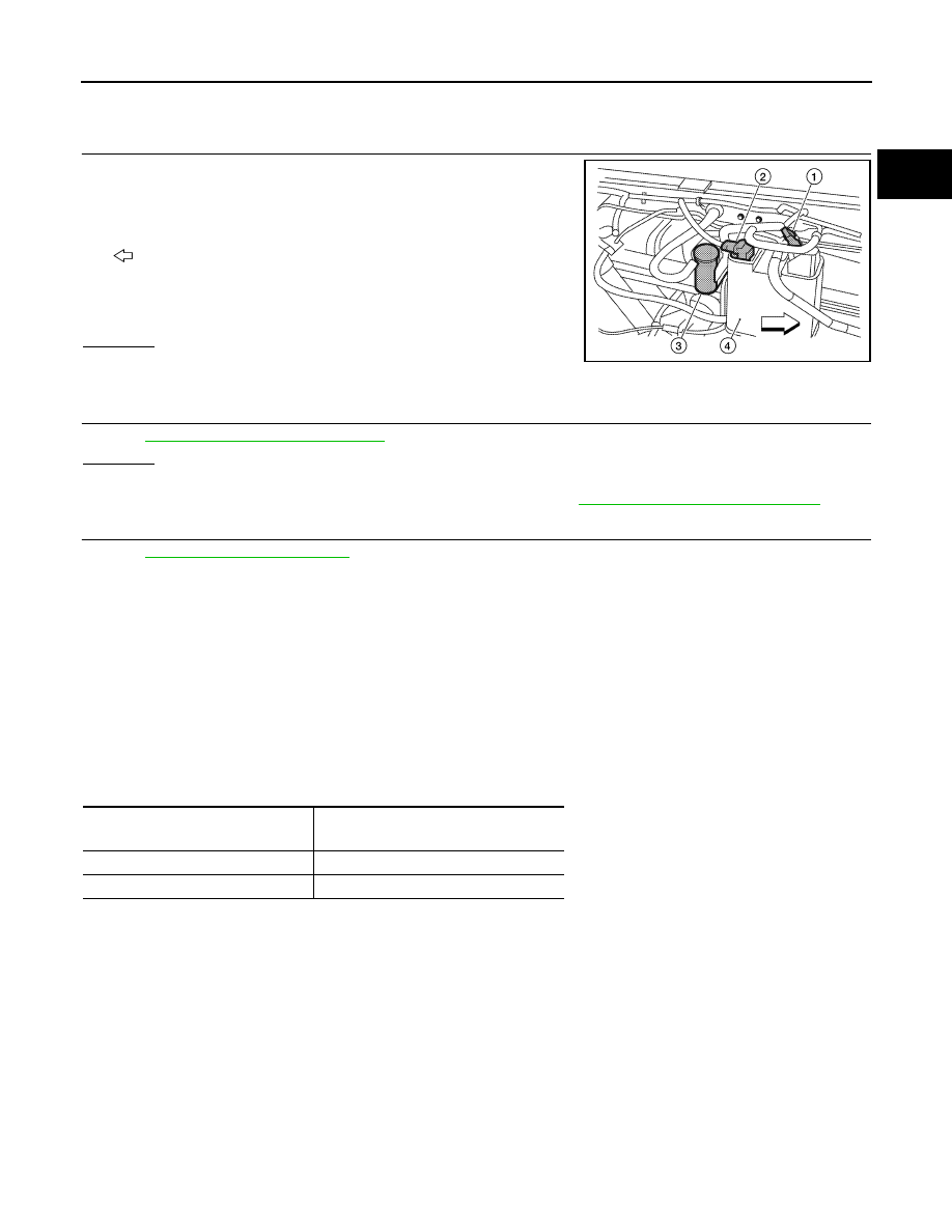
1. Disconnect EVAP control system pressure sensor (2) harness
connector.
-
EVAP canister vent control valve (1)
-
Drain filter (3)
-
EVAP canister (4)
-
: Vehicle front
2. Check sensor harness connector for water.
OK or NG
OK
>> GO TO 3.
NG
>> Repair or replace harness connector.
3.
CHECK EVAP CONTROL SYSTEM PRESSURE SENSOR
EC-783, "Component Inspection"
OK or NG
OK
>> GO TO 4.
NG
>> Replace EVAP control system pressure sensor. Refer to
FL-14, "Removal and Installation"
.
4.
CHECK INTERMITTENT INCIDENT
GI-42, "Intermittent Incident"
.
>> INSPECTION END
Component Inspection
INFOID:0000000009481442
EVAP CONTROL SYSTEM PRESSURE SENSOR
1. Remove EVAP control system pressure sensor with its harness connector connected from EVAP canister.
Do not reuse the O-ring, replace it with a new one.
2. Install a vacuum pump to EVAP control system pressure sensor.
3. Turn ignition switch ON and check output voltage between ECM terminal 102 and ground under the fol-
lowing conditions.
CAUTION:
• Always calibrate the vacuum pump gauge when using it.
• Never apply below -93.3 kPa (-0.952 kg/cm
2
, -13.53 psi) or pressure over 101.3 kPa (1.033 kg/cm
2
,
14.69 psi).
4. If NG, replace EVAP control system pressure sensor.
Water should not exist.
ALBIA0514ZZ
Applied vacuum kPa
(kg/cm
2
, psi)
Voltage V
Not applied
1.8 - 4.8
-26.7 (-0.272, -3.87)
2.1 to 2.5V lower than above value