Nissan Frontier. Instruction - part 455
P1572 ASCD BRAKE SWITCH
EC-391
< DTC/CIRCUIT DIAGNOSIS >
[QR25DE]
C
D
E
F
G
H
I
J
K
L
M
A
EC
N
P
O
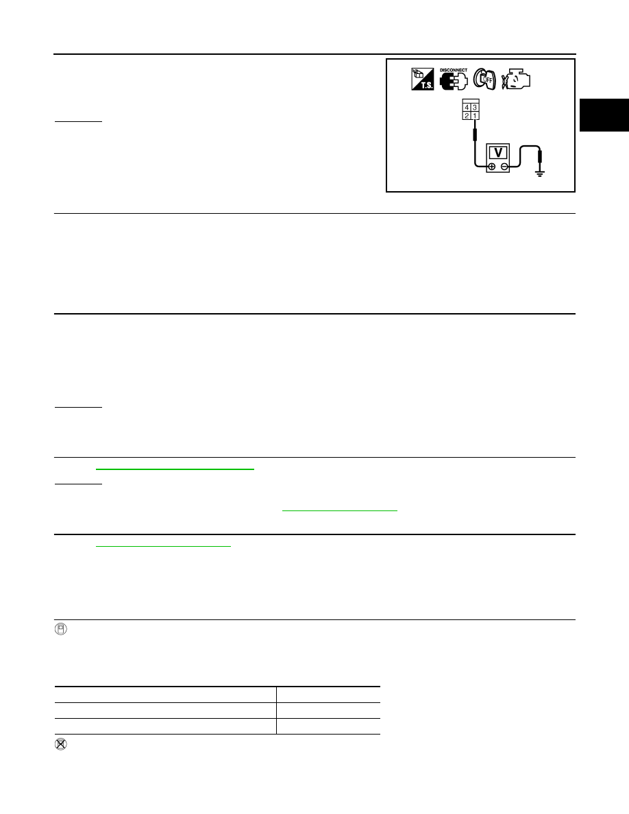
3. Check voltage between stop lamp switch terminal 1 and ground
with CONSULT or tester.
OK or NG
OK
>> GO TO 9.
NG
>> GO TO 8.
8.
DETECT MALFUNCTIONING PART
Check the following.
• Fuse block (J/B) connector E160
• 10A fuse (No.20)
• Harness for open or short between stop lamp switch and battery
>> Repair open circuit, short to ground or short to power in harness or connectors.
9.
CHECK STOP LAMP SWITCH INPUT SIGNAL CIRCUIT FOR OPEN AND SHORT
1. Disconnect ECM harness connector.
2. Check harness continuity between ECM terminal 106 and stop lamp switch terminal 2.
Refer to Wiring Diagram.
3. Also check harness for short to ground and short to power.
OK or NG
OK
>> GO TO 10.
NG
>> Repair open circuit, short to ground or short to power in harness or connectors.
10.
CHECK STOP LAMP SWITCH
EC-395, "Component Inspection"
OK or NG
OK
>> GO TO 11.
NG
>> Replace stop lamp switch. Refer to
.
11.
CHECK INTERMITTENT INCIDENT
GI-42, "Intermittent Incident"
.
>> INSPECTION END
M/T MODELS
1.
CHECK OVERALL FUNCTION-I
With CONSULT
1. Turn ignition switch ON.
2. Select “BRAKE SW1” in “DATA MONITOR” mode with CONSULT.
3. Check “BRAKE SW1” indication under the following conditions.
Without CONSULT
1. Turn ignition switch ON.
2. Check voltage between ECM terminal 110 and ground under the following conditions.
Voltage: Battery voltage
PBIB1184E
Continuity should exist.
CONDITION
INDICATION
Brake pedal and/or clutch pedal: Slightly depressed
OFF
Brake pedal and clutch pedal: Fully released
ON