Nissan Frontier. Instruction - part 279


  Index      Nissan     Nissan Frontier (2014 year) - Service and Repair Instruction


Search            copyright infringement  


Content   ..  277  278  279  280   ..


Nissan Frontier. Instruction - part 279


DLN-18

< SYSTEM DESCRIPTION >

[TRANSFER: TX15B]

DIAGNOSIS SYSTEM (TRANSFER CONTROL UNIT)

Refer to "Judgement Self-diagnosis".

Diagnostic Procedure (M/T models)

1. Warm up engine.
2. Turn ignition switch “ON” and “OFF” at least twice, and then turn ignition switch “OFF”.
3. Move M/T shift lever to neutral position.
4. Turn 4WD shift switch to “2WD” position.
5. Turn ignition switch “ON”. (Do not start engine.)
6. 4WD warning lamp should turn ON.

If 4WD warning lamp does not turn ON, refer to 

DLN-73, "Diagnosis Procedure"

.

7. Move M/T shift lever to any position other than neutral.
8. Turn 4WD shift switch to “2WD”, “4H” and “2WD” in order.
9. Move M/T shift lever to neutral position.
10. Turn 4WD shift switch to “4H”, “2WD” and “4H” in order.
11. Move M/T shift lever to any position other than neutral.
12. Turn 4WD shift switch to “2WD” position.
13. Move M/T shift lever to neutral position.
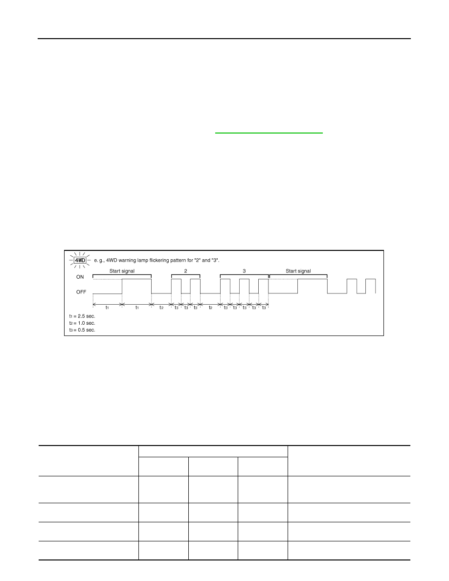
14. Read the flickering of 4WD warning lamp.

Refer to "Judgement Self-diagnosis".

Self-diagnosis example

DATA MONITOR

Operation Procedure

1. Connect “CONSULT.”
2. Touch “DATA MONITOR”.
3. Select from “SELECT MONITOR ITEM”, screen of data monitor mode is displayed.

NOTE:

When malfunction is detected, CONSULT performs REAL-TIME DIAGNOSIS.

Also, any malfunction detected while in this mode will be displayed at real time.

×: Standard –: Not applicable

PDIA0227E

Monitor Item (Unit)

Selection

Description

ECU INPUT 

SIGNALS

MAIN

SIGNALS

SELECTION 

FROM MENU

VHCL/S SEN-FR [km/h] or [mph]

×

×

Wheel speed calculated by ABS actuator 
and electric unit (control unit).
Signal input with CAN communication line.

VHCL/S SEN-RR [km/h] or [mph]

×

×

Wheel speed calculated by TCM.
Signal input with CAN communication line.

ENGINE SPEED [rpm]

×

×

Engine speed is displayed.
Signal input with CAN communication line.

BATTERY VOLT [V]

×

×

Power supply voltage for transfer control 
unit.

DIAGNOSIS SYSTEM (TRANSFER CONTROL UNIT)

DLN-19

< SYSTEM DESCRIPTION >

[TRANSFER: TX15B]

C

E

F

G

H

I

J

K

L

M

A

B

DLN

N

O

P

2WD SWITCH [On/Off]

×

×

4WD shift switch signal status is displayed.
(4L means 4LO of 4WD shift switch.)

4H SWITCH [On/Off]

×

×

4L SWITCH [On/Off]

×

×

4L POSI SW [On/Off]

×

×

4LO switch signal status is displayed.

ATP SWITCH [On/Off]

×

×

ATP switch signal status is displayed.

WAIT DETCT SW [On/Off]

×

×

Wait detection switch signal status is dis-
played.

4WD MODE [2H/4H/4L]

×

×

Control status of 4WD recognized by trans-
fer control unit. (2WD, 4H or 4LO)

VHCL/S COMP [km/h] or [mph]

×

×

Vehicle speed recognized by transfer con-
trol unit.

SHIFT ACT 1 [On/Off]

×

×

Output condition to actuator motor (clock-
wise)

SHIFT AC MON1 [On/Off]

×

Check signal for transfer control unit signal 
output

SHIFT ACT 2 [On/Off]

×

×

Output condition to actuator motor (coun-
terclockwise)

SHIFT AC MON2 [On/Off]

×

Check signal for transfer control unit signal 
output

SFT ACT/R MON [On/Off]

×

Operating condition of actuator motor relay 
(integrated in transfer control unit)

SHIFT POS SW1 [On/Off]

×

×

Condition of actuator position switch 1

SHIFT POS SW2 [On/Off]

×

×

Condition of actuator position switch 2

SHIFT POS SW3 [On/Off]

×

×

Condition of actuator position switch 3

SHIFT POS SW4 [On/Off]

×

×

Condition of actuator position switch 4

4WD FAIL LAMP [On/Off]

×

×

Control status of 4WD warning lamp is dis-
played.

2WD IND [On/Off]

×

Control status of 4WD shift indicator lamp 
(rear) is displayed.

4H IND [On/Off]

×

Control status of 4WD shift indicator lamp 
(front and center) is displayed.

4L IND [On/Off]

×

Control status of 4LO indicator lamp is dis-
played.

Monitor Item (Unit)

Selection

Description

ECU INPUT 

SIGNALS

MAIN

SIGNALS

SELECTION 

FROM MENU

DLN-20

< SYSTEM DESCRIPTION >

[TRANSFER: TX15B]

NOISE, VIBRATION AND HARSHNESS (NVH) TROUBLESHOOTING

NOISE, VIBRATION AND HARSHNESS (NVH) TROUBLESHOOTING

NVH Troubleshooting Chart

INFOID:0000000009479633

Use the chart below to help you find the cause of the symptom. The numbers indicate the order of the inspec-

tion. If necessary, repair or replace these parts.

Reference page

DLN-90

DLN-103

DLN-103

DLN-103

DLN-103

SUSPECTED PARTS
(Possible cause)

T

R

ANSFER F

LUID (Level

 low)

T

R

ANSFER F

LUID (W

rong)

T

R

ANSFER F

LUID (Level

 too high)

LI

QUI

D

 GASKET (Dam

ag

ed

)

O-RI

NG (W

orn

 or da

ma

ge

d)

OIL

 SEAL

 (W

orn

 or da

ma

ge

d)

S

H

IFT 

FO

RK

 (W

orn

 or d

am

a

ged

)

GEAR (W

orn

 o

r da

ma

ge

d)

B

EARING

 (W

orn

 or 

da

ma

ge

d)

Symptom

Noise

1

2

3

3

Transfer  fluid  leakage

3

1

2

2

2

Hard to shift or will not shift

1

1

2

P1801, P1811 POWER SUPPLY CIRCUIT FOR TRANSFER CONTROL UNIT

DLN-21

< DTC/CIRCUIT DIAGNOSIS >

[TRANSFER: TX15B]

C

E

F

G

H

I

J

K

L

M

A

B

DLN

N

O

P

DTC/CIRCUIT DIAGNOSIS

P1801, P1811 POWER SUPPLY CIRCUIT FOR TRANSFER CONTROL
UNIT

Description

INFOID:0000000009479634

The transfer control unit controls the transfer control device which controls shifts between 4H and 4LO and

between 2WD and 4WD. When the vehicle battery is removed, the power supply to the transfer control unit is

interrupted, and self-diagnosis memory function is suspended. These DTCs may also set when the power

supply voltage for the transfer control unit is abnormally low while driving.

DTC Logic

INFOID:0000000009479635

DTC DETECTION LOGIC

DTC CONFIRMATION PROCEDURE

1.

DTC CONFIRMATION PROCEDURE

1. Turn ignition switch ON.

2. Perform self-diagnosis.
Are DTCs “P1801 or P1811 detected?

YES

>> Perform diagnosis procedure. Refer to 

DLN-21, "Diagnosis Procedure"

.

NO

>> Inspection End.

Diagnosis Procedure

INFOID:0000000009479636

Regarding Wiring Diagram information, refer to 

DLN-63, "Wiring Diagram"

.

1.

CHECK POWER SUPPLY

1. Turn ignition switch “OFF”. (Stay for at least 5 seconds.)

2. Disconnect transfer control unit harness connector.

3. Check voltage between transfer control unit harness connector

terminals and ground.

DTC

CONSULT

Diagnostic item is detected when...

Reference

[P1801]

*INITIAL START*

Due to removal of battery which cuts off 
power supply to transfer control unit, 
self-diagnosis memory function is sus-
pended.

DLN-21

[P1811]

BATTERY VOLTAGE

Power supply voltage for transfer control 
unit is abnormally low while driving.

Connector

Terminal

Voltage (Approx.)

M152

19 - Ground

Battery voltage

25 - Ground

0V

M153

40 - Ground

Battery voltage

44 - Ground

0V

45 - Ground

SDIA3360E


Content   ..  277  278  279  280   ..