Nissan Frontier. Instruction - part 1156


  Index      Nissan     Nissan Frontier (2014 year) - Service and Repair Instruction


Search            copyright infringement  


Content   ..  1154  1155  1156  1157   ..


Nissan Frontier. Instruction - part 1156


SR-14

< REMOVAL AND INSTALLATION >

SPIRAL CABLE

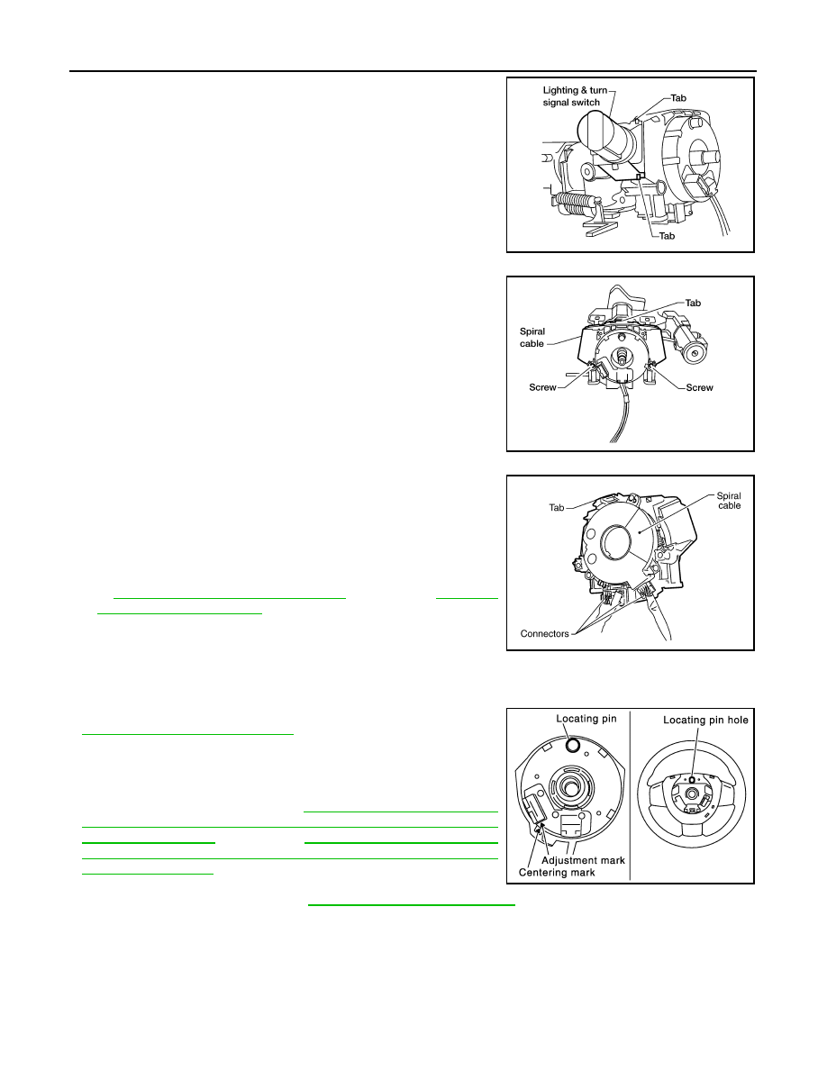
6. Disconnect lighting and turn signal switch connector. Then while

pressing tabs, pull lighting and turn signal switch toward driver

door to remove.

7. Remove the screws. Then while pressing the tab, pull the spiral

cable away from steering column assembly. 

CAUTION:

• Do not disassemble spiral cable.

• Do not apply lubricant to the spiral cable.

8. Disconnect the harness connectors from the spiral cable.

CAUTION:

With the steering linkage disconnected, the spiral cable

may snap by turning the steering wheel beyond the limited

number of turns. The spiral cable can be turned counter-

clockwise about 2.5 turns from the neutral position.

9. Remove the steering angle sensor from the spiral cable. Refer

to 

BRC-117, "Removal and Installation"

 (TYPE 1) or  

BRC-238,

"Removal and Installation"

 (TYPE 2).

INSTALLATION

Installation is in the reverse order of removal.

• Align spiral cable correctly when installing steering wheel, refer to

ST-11, "Removal and Installation"

. Make sure that the spiral cable

is in the neutral position. The neutral position is detected by turning

left 2.5 revolutions from the right end position and ending with the

locating pin at the top.

• Reset the steering angle sensor (if equipped) calibration after

installing spiral cable. Refer to 

BRC-12, "ADJUSTMENT OF

STEERING ANGLE SENSOR NEUTRAL POSITION : Special

Repair Requirement"

 (TYPE 1) or 

BRC-124, "ADJUSTMENT OF

STEERING ANGLE SENSOR NEUTRAL POSITION : Special

Repair Requirement"

 (TYPE 2).

• After the work is completed, perform self-diagnosis to make sure

no malfunction is detected. Refer to 

SRC-13, "SRS Operation Check"

.

CAUTION:

• The spiral cable may snap due to steering operation if the cable is not installed in the correct posi-

tion.

• With the steering linkage disconnected, the cable may snap by turning the steering wheel beyond

the limited number of turns. The spiral cable can be turned counterclockwise about 2.5 turns from

the neutral position.

LHIA0035E

LHIA0036E

LHIA0088E

PHIA0275E

FRONT PASSENGER AIR BAG MODULE

SR-15

< REMOVAL AND INSTALLATION >

C

D

E

F

G

I

J

K

L

M

A

B

SR

N

O

P

FRONT PASSENGER AIR BAG MODULE

Removal and Installation

INFOID:0000000009480300

The passenger air bag module originally installed in the vehicle uses direct-connect style harness connectors.

Service replacement passenger air bag modules use tab-locking style harness connectors. If the passenger

air bag module is replaced or if the direct-connect harness connectors are damaged, the vehicle wiring har-

ness must be modified to allow connection of the service replacement passenger air bag module. See "WIR-

ING HARNESS MODIFICATION" for wiring harness modification procedure.

REMOVAL

CAUTION:

• Do not attempt to repair or replace damaged direct-connect front passenger air bag module connec-

tors. If a direct-connect harness connector is damaged, the front passenger air bag must be

replaced and the wiring harness modified.

• Before servicing SRS, turn the ignition switch off, disconnect both battery terminals and wait at least

three minutes.

• Always work from the side of or under front passenger air bag module.
1. Disconnect the negative and positive battery terminals, then wait at least three minutes. Refer to 

PG-83,

"Removal and Installation"

.

2. Remove the upper glove box. Refer to 

IP-23, "Removal and Installation"

.

3. Remove two bolts (through glove box opening) retaining front

passenger air bag module to the steering member.

4. Disconnect the passenger air bag module connectors. 

• For removal/installation of the direct-connect SRS connectors,

refer to 

SRC-9, "Direct-connect SRS Component Connectors"

.

5. Remove the instrument panel assembly. Refer to 

IP-15,

"Removal and Installation"

6. Remove front passenger air bag module screws then remove

passenger air bag module from instrument panel assembly.

CAUTION:

LHIA0093E

WHIA0269E

SR-16

< REMOVAL AND INSTALLATION >

FRONT PASSENGER AIR BAG MODULE

• When servicing the SRS, do not work from directly in front of

air bag module.

• Always place front passenger air bag module with caution

label side facing upward.

• Do not insert any foreign objects (screwdriver, etc.) into air

bag module or harness connectors.

• Do not disassemble air bag module. 

• Do not use old nuts after removal; replace with new nuts.

• Do not expose the front passenger air bag module to tempera-

tures exceeding 90

°C (194°F).

• Replace the air bag module if it has been dropped or sus-

tained an impact.

• Do not allow oil, grease or water to come in contact with the

air bag module.

• For removal/installation of the direct-connect SRS connec-

tors, refer to 

SRC-9, "Direct-connect SRS Component Con-

nectors"

.

INSTALLATION

Original Passenger Air Bag Module

Installation is in the reverse order of removal.

• For removal/installation of the direct-connect SRS connectors, refer to 

SRC-9, "Direct-connect SRS Compo-

nent Connectors"

.

CAUTION:

• Always work from the side of or under front passenger air bag module.

• After the work is completed, perform self-diagnosis to check that no malfunction is detected. Refer

to 

SRC-13, "SRS Operation Check"

.

Service Replacement Passenger Air Bag Module

1. Install the front passenger air bag module to the instrument

panel pad assembly.

2. Install the instrument panel assembly. Refer to 

IP-15, "Removal and Installation"

.

3. Connect the front passenger air bag module harness connector to yellow 4-pin service replacement air

bag connector and fasten connector to mounting bracket. 

CAUTION:

• Always work from the side of or under front passenger air bag module.

• After the work is completed, perform self-diagnosis to check that no malfunction is detected. Refer

to 

SRC-13, "SRS Operation Check"

.

WIRING HARNESS MODIFICATION

The passenger air bag module originally installed in the vehicle uses direct-connect style harness connectors.

Service replacement passenger air bag modules use tab-locking style harness connectors. If the passenger

WHIA0111E

SBF814E

WHIA0269E

FRONT PASSENGER AIR BAG MODULE

SR-17

< REMOVAL AND INSTALLATION >

C

D

E

F

G

I

J

K

L

M

A

B

SR

N

O

P

air bag module is replaced or if the direct-connect harness connectors are damaged, the vehicle wiring har-

ness must be modified to allow connection of the service replacement passenger air bag module.

NOTE:

The wiring harness modification is to be performed only if the vehicle is equipped with the original passenger

air bag which uses direct-connect harness connectors. If the passenger air bag is to be replaced in a vehicle

that has already had the service replacement passenger air bag installed, the wiring harness modification is

not required.

CAUTION:

• Do not attempt to repair or replace damaged direct-connect front passenger air bag module connec-

tors. If a direct-connect harness connector is damaged, the front passenger air bag must be

replaced and the wiring harness modified.

• Before servicing SRS, turn the ignition switch off, disconnect both battery cables and wait at least

three minutes.

• Always work from the side of or under front passenger air bag module.

• After the work is completed, perform self-diagnosis to check that no malfunction is detected. Refer

to 

SRC-13, "SRS Operation Check"

.

1. Locate the yellow and orange direct-connect passenger air bag module harness connectors.
2. Use wire cutters to cut back both previously used direct-connect passenger air bag module harness con-

nectors from the vehicle wiring harness approximately 50 mm (1.9 in) from the connectors.

3. Remove approximately 150 mm (5.9 in) of the vehicle harness covering from the cut end.
4. Slide a piece of dual-wall heat shrink tubing (provided in the pas-

senger air bag service kit) onto each wire of the previously used

vehicle wiring harness.

5. Fold each wire back and insert into the end of the heat shrink

tubing so that the end of the wire is approximately centered in

the heat shrink tubing.

6. Use a heat gun to shrink the heat shrink tubing and seal the wire.
7. Use electrical tape to secure the modified circuits to the outside of the wiring harness.
8. Locate the front passenger air bag service replacement connec-

tor that is taped back to the main harness. Unwrap the tape to

access the yellow service replacement connector and remove

the dust cover from the connector.

LHIA0017E

WHIA0062E

WHIA0118E


Content   ..  1154  1155  1156  1157   ..