Nissan Leaf. Instruction - part 887
LAN-10
< SYSTEM DESCRIPTION >
[CAN FUNDAMENTAL]
TROUBLE DIAGNOSIS
TROUBLE DIAGNOSIS
Component Description
INFOID:0000000010120350
Condition of Error Detection
INFOID:0000000010120351
DTC (e.g. U1000 and U1001) of CAN communication is indicated on SELF-DIAG RESULTS on CONSULT if a
CAN communication signal is not transmitted or received between units for 2 seconds or more.
CAN COMMUNICATION SYSTEM ERROR
• CAN communication line open (CAN-H, CAN-L, or both)
• CAN communication line short (ground, between CAN communication lines, other harnesses)
• Error of CAN communication control circuit of the unit connected to CAN communication line
WHEN DTC OF CAN COMMUNICATION IS INDICATED EVEN THOUGH CAN COMMUNICATION
SYSTEM IS NORMAL
• Removal/installation of parts: Error may be detected when removing and installing CAN communication unit
and related parts while turning the ignition switch ON. (A DTC except for CAN communication may be
detected.)
• Fuse blown out (removed): CAN communication of the unit may cease.
• Voltage drop: Error may be detected if voltage drops due to discharged 12V battery when turning the ignition
switch ON (Depending on the control unit which carries out CAN communication).
• Error may be detected if the power supply circuit of the control unit, which carries out CAN communication,
malfunctions (Depending on the control unit which carries out CAN communication).
• Error may be detected if reprogramming is not completed normally.
NOTE:
CAN communication system is normal if DTC of CAN communication is indicated on SELF-DIAG RESULTS of
CONSULT under the above conditions. Erase the memory of the self-diagnosis of each control unit.
JSMIA0527GB
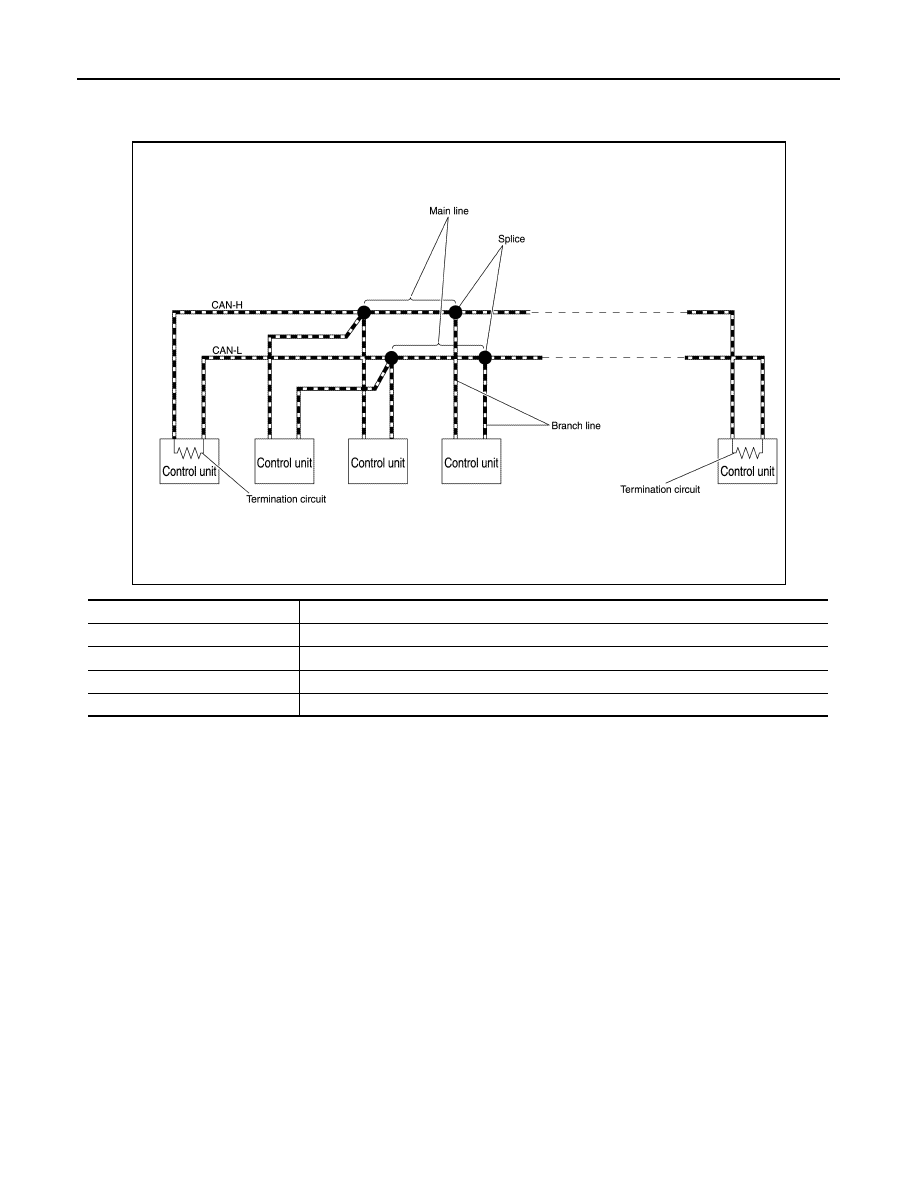
Component
Description
Main line
CAN communication line between splices
Branch line
CAN communication line between splice and a control unit
Splice
A point connecting a branch line with a main line
Termination circuit
Circuit connected across the CAN communication system. (Resistor)