Nissan Leaf. Instruction - part 692
TRANSVERSE LINK
FSU-17
< REMOVAL AND INSTALLATION >
C
D
F
G
H
I
J
K
L
M
A
B
FSU
N
O
P
TRANSVERSE LINK
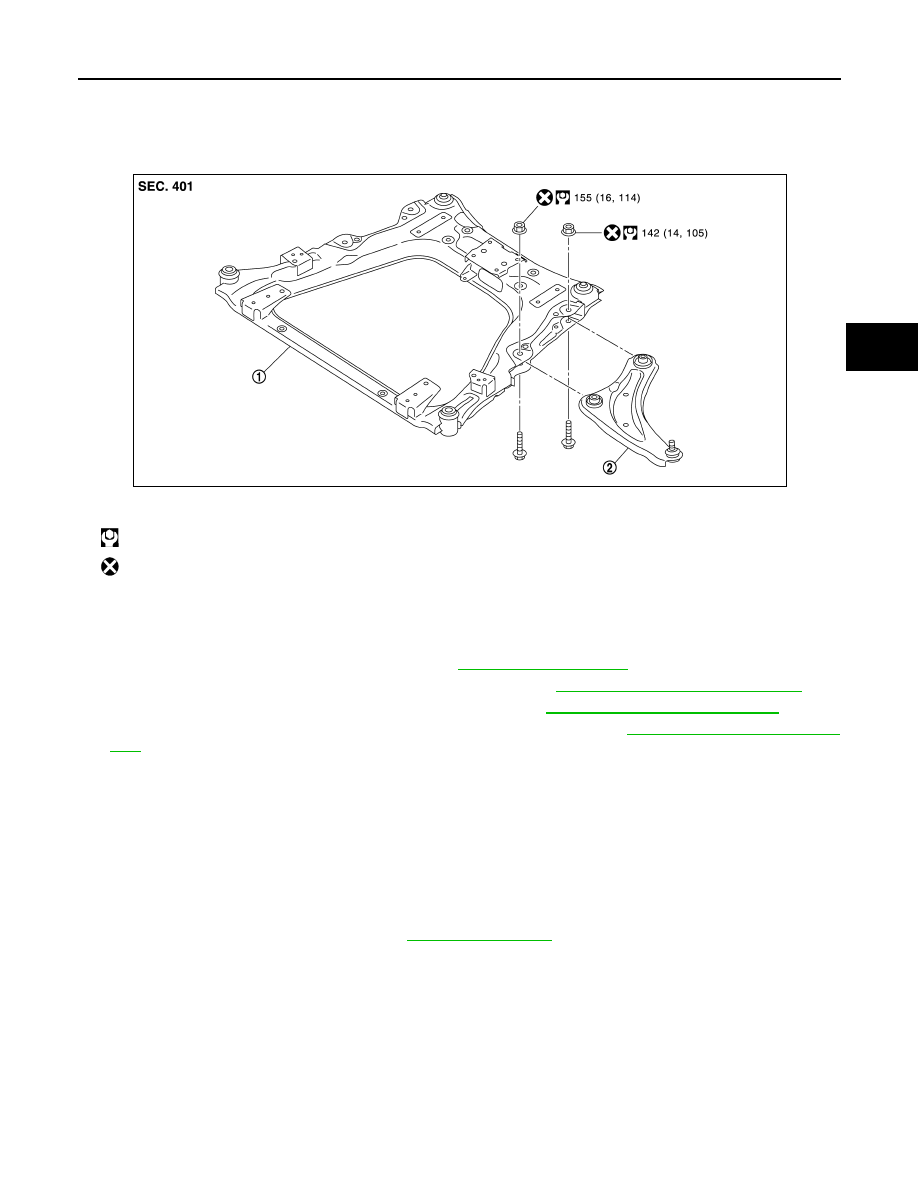
Exploded View
INFOID:0000000010119435
Removal and Installation
INFOID:0000000010119436
REMOVAL
1. Remove wheel and tire using power tool. Refer to
2. Separate stabilizer connecting rod from strut assembly. Refer to
FSU-19, "Removal and Installation"
3. Separate steering outer socket from steering knuckle. Refer to
ST-41, "Removal and Installation"
.
4. Remove transverse link from steering knuckle using power tool. Refer to
5. Remove transverse link from suspension member using power tool.
NOTE:
To remove transverse link nut, move stabilizer bar.
INSTALLATION
Note the following, and install in the reverse order of removal.
CAUTION:
Do not reuse transverse link nuts.
• Perform final tightening of fixing parts at the vehicle installation position (rubber bushing), under unladen
conditions with tires on level ground.
• Perform inspection after installation. Refer to
.
Inspection
INFOID:0000000010119437
INSPECTION AFTER REMOVAL
Check the following items, and replace the parts if necessary.
Transverse Link
• Transverse link and bushing for deformation, cracks or damage.
• Ball joint boot for cracks or other damage, and also for grease leakage.
Swing Torque
1. Instructionly move ball stud to confirm it moves smoothly with no binding.
1.
Front suspension member
2.
Transverse link
: N·m (kg-m, ft-lb)
: Always replace after every disassembly.
JPEIA0286GB