Content .. 1140 1141 1142 1143 ..
Nissan Leaf. Instruction - part 1142
EPS CONTROL UNIT
STC-13
< ECU DIAGNOSIS INFORMATION >
C
D
E
F
H
I
J
K
L
M
A
B
STC
N
O
P
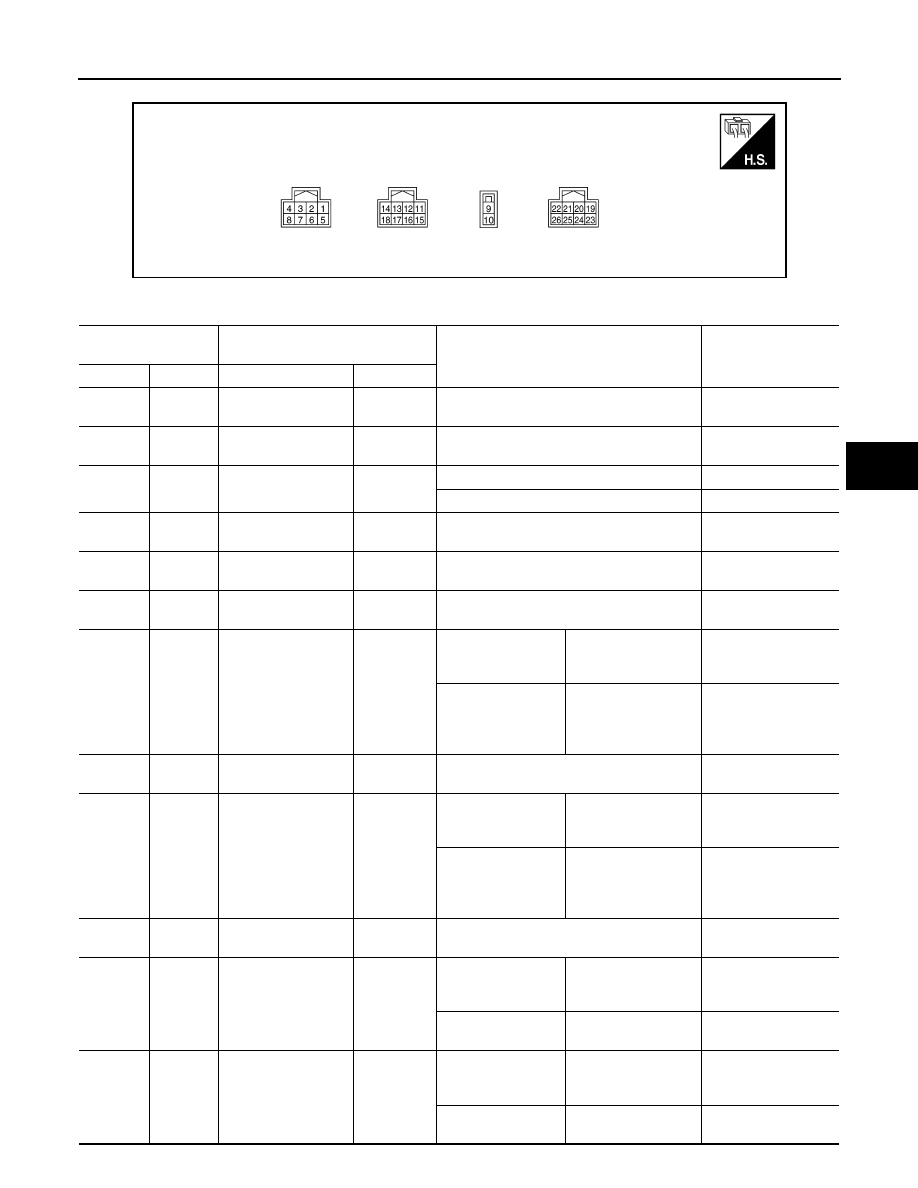
TERMINAL LAYOUT
PHYSICAL VALUES
ALGIA0178ZZ
Terminal No.
(Wire Color)
Description
Condition
Value
(Approx.)
+
−
Signal name
Input/Output
1
(P)
—
CAN-L
Input/Output
—
—
2
(L)
—
CAN-H
Input/Output
—
—
4
(W)
Ground
Ignition power supply
Input
Ignition switch: ON
Battery voltage
Ignition switch: OFF
0 V
9
(R)
Ground
Battery power supply
Input
Always
Battery voltage
10
(B)
Ground
Ground
—
Always
0 V
11
(B)
Ground
Torque sensor ground
Input
Always
0 V
12
(Y)
Ground
Torque sub sensor
signal
Input
Ignition switch: ON
Steering wheel: Not
steering (There is no
steering force)
2.5 V
Engine running
Steering wheel: steer-
ing
1.6 V – 3.4 V
(The value is changed
according to steering
left or right)
14
(R)
Ground
Torque sensor power
supply
Output
Ignition switch: ON
10 V
15
(G)
Ground
Torque main sensor
signal
Input
Ignition switch: ON
Steering wheel: Not
steering (There is no
steering force)
2.5 V
Engine running
Steering wheel: steer-
ing
1.6 V – 3.4 V
(The value is changed
according to steering
left or right)
17
(W)
Ground
Torque sensor refer-
ence voltage
Output
Ignition switch: ON
3.3 V
19
(G)
Ground
Reference signal R2
Input
Ignition switch: ON
Steering wheel: Not
steering (There is no
steering force)
—
Engine running
Steering wheel: steer-
ing
—
22
(W)
Ground
Reference signal R1
Input
Ignition switch: ON
Steering wheel: Not
steering (There is no
steering force)
—
Engine running
Steering wheel: steer-
ing
—