Content .. 1026 1027 1028 1029 ..
Nissan Leaf. Instruction - part 1028
PWC-30
< DTC/CIRCUIT DIAGNOSIS >
POWER SUPPLY AND GROUND CIRCUIT
DTC/CIRCUIT DIAGNOSIS
POWER SUPPLY AND GROUND CIRCUIT
BCM
BCM : Diagnosis Procedure
INFOID:0000000010503115
Regarding Wiring Diagram information, refer to
.
1.
CHECK FUSE AND FUSIBLE LINK
Check that the following fuse and fusible link are not blown.
Is the fuse or fusible link blown?
YES
>> Replace the blown fuse or fusible link after repairing the affected circuit.
NO
>> GO TO 2.
2.
CHECK POWER SUPPLY CIRCUIT
1. Disconnect BCM connector M25.
2. Check voltage between BCM connector M25 and ground.
Is the inspection result normal?
YES
>> GO TO 3.
NO
>> Repair or replace harness or connectors.
3.
CHECK GROUND CIRCUIT
Check continuity between BCM connector M25 and ground.
Is the inspection result normal?
YES
>> Inspection End.
NO
>> Repair or replace harness or connectors.
POWER WINDOW MAIN SWITCH
POWER WINDOW MAIN SWITCH : Diagnosis Procedure
INFOID:0000000010119947
Regarding Wiring Diagram information, refer to
.
1.
CHECK MAIN POWER WINDOW AND DOOR LOCK/UNLOCK SWITCH POWER SUPPLY
1. Turn power switch OFF.
2. Disconnect main power window and door lock/unlock switch connector.
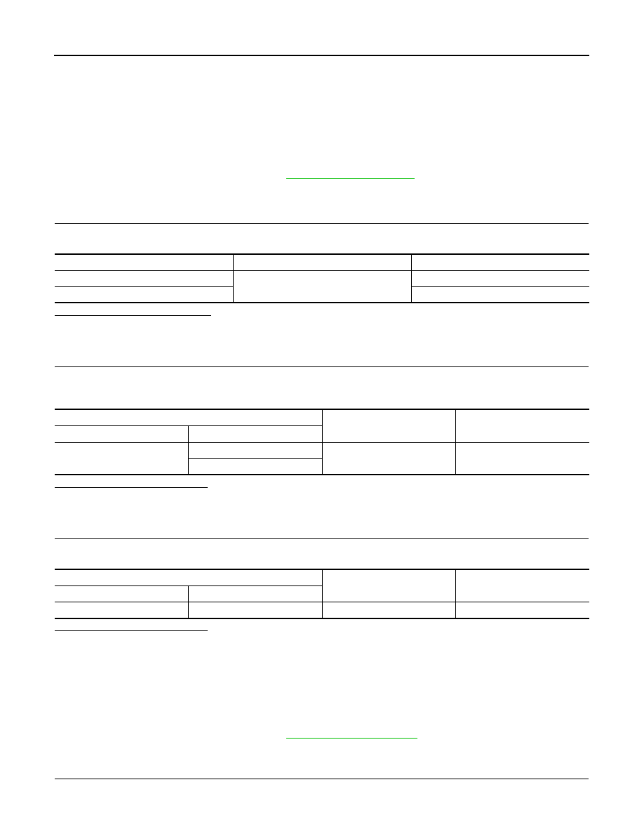
Terminal No.
Signal name
Fuse and fusible link No.
57
Battery power supply
9 (10A)
70
H (40A)
BCM
Ground
Voltage
(Approx.)
Connector
Terminal
M25
57
—
Battery voltage
70
BCM
Ground
Continuity
Connector
Terminal
M25
67
—
Yes