Nissan Xterra. Instruction - part 281
EC-250
< DTC/CIRCUIT DIAGNOSIS >
[VQ40DE]
P0181 FTT SENSOR
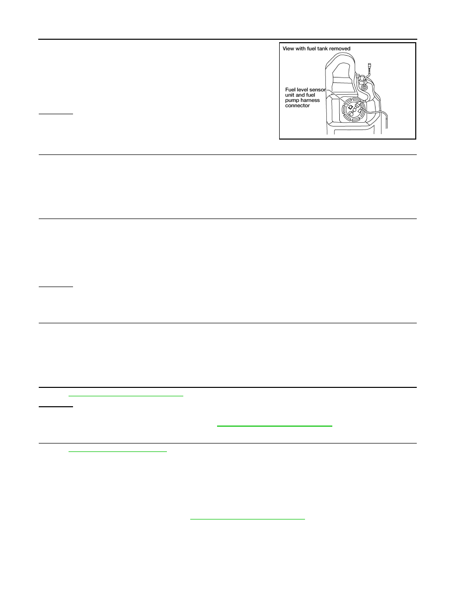
2. Disconnect “fuel level sensor unit and fuel pump” harness con-
nector.
3. Turn ignition switch ON.
4. Check voltage between “fuel level sensor unit and fuel pump”
terminal 4 and ground with CONSULT or tester.
OK or NG
OK
>> GO TO 5.
NG
>> GO TO 4.
4.
DETECT MALFUNCTIONING PART
Check the following.
• Harness connectors E41, C1
• Harness for open or short between ECM and “fuel level sensor unit and fuel pump”
>> Repair harness or connector.
5.
CHECK FUEL TANK TEMPERATURE SENSOR GROUND CIRCUIT FOR OPEN AND SHORT
1. Turn ignition switch OFF.
2. Check harness continuity between “fuel level sensor unit and fuel pump” terminal 3 and ground. Refer to
Wiring Diagram.
3. Also check harness for short to power.
OK or NG
OK
>> GO TO 7.
NG
>> GO TO 6.
6.
DETECT MALFUNCTIONING PART
Check the following.
• Harness connectors E41, C1
• Harness for open or short between “fuel level sensor unit and fuel pump” and ground
>> Repair open circuit or short to power in harness or connector.
7.
CHECK FUEL TANK TEMPERATURE SENSOR
EC-250, "Component Inspection"
OK or NG
OK
>> GO TO 8.
NG
>> Replace fuel level sensor unit. Refer to
FL-11, "Removal and Installation"
8.
CHECK INTERMITTENT INCIDENT
GI-40, "Intermittent Incident"
>> INSPECTION END
Component Inspection
INFOID:0000000009483950
FUEL TANK TEMPERATURE SENSOR
1. Remove fuel level sensor unit. Refer to
FL-11, "Removal and Installation"
.
Voltage: Approximately 5V
BBIA0545E
Continuity should exist.