Nissan Armada (2019 year). Manual - part 16
SAA3059
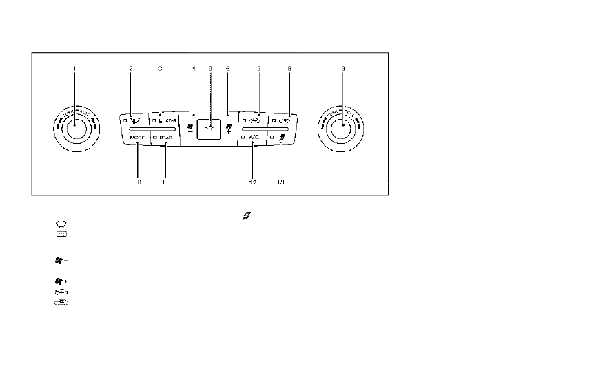
1.
“AUTO” button/Temperature control dial
(driver’s side)
2.
“
” front defroster button
3.
“
” rear window defroster button (See
“Rear window and outside mirror defros-
ter switch” (P.2-36).)
4.
“
” fan speed decrease button
5.
“OFF” button
6.
“
” fan speed increase button
7.
“
” outside air circulation button
8.
“
” air recirculation button
9.
“DUAL” zone control ON/OFF button/
Temperature control dial (passenger’s
side)
10.
“MODE” manual air flow control button
11.
“REAR” control button
12.
“A/C” air conditioner ON/OFF button
13.
“
” upper vent button
AUTOMATIC AIR CONDITIONER
Automatic operation
Cooling and/or dehumidified heating
(AUTO):
This mode may be used all year round.
The system works automatically to con-
trol the inside temperature, air flow dis-
tribution and fan speed after the
preferred temperature is set manually.
1.
Push the “AUTO” button on. (The
indicator on the button will illuminate
and AUTO will be displayed.)
2.
Turn the temperature control dial
(driver’s side) to set the desired tem-
perature.
The temperature of the passenger
compartment will be maintained
automatically. Air flow distribution
and fan speed will also be controlled
automatically.
3. You can individually set driver and
front passenger’s side temperature
using each temperature control but-
ton. When the “DUAL” button is pushed
or the passenger’s side temperature
control button is turned, the DUAL
indicator will come on. To turn off the
passenger’s side temperature control,
push the “DUAL” button.
Monitor, heater, air conditioner, audio, phone and voice recognition systems
4-35