содержание .. 243 244 245 246 ..
Nissan GT-R. Instruction - part 245
PWC-30
< DTC/CIRCUIT DIAGNOSIS >
DOOR SWITCH CIRCUIT
3.
Check continuity between malfunctioning power window motor harness connector and ground.
Is the inspection result normal?
YES
>> GO TO 4.
NO
>> Repair or replace harness.
4.
CHECK INTERMITTENT INCIDENT
GI-38, "Intermittent Incident"
>> INSPECTION END
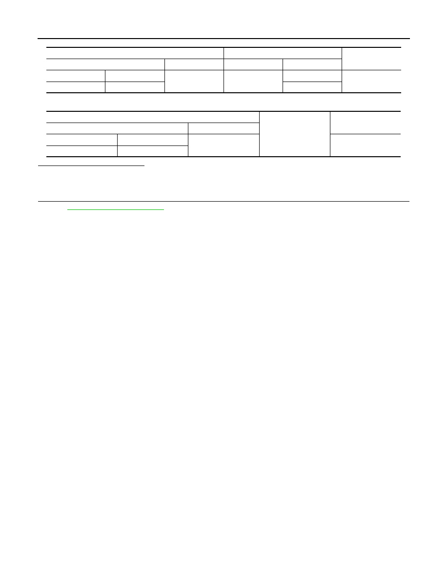
Power window motor
BCM
Continuity
Connector
Terminal
Connector
Terminal
Driver side
D10
6
M123
150
Existed
Passenger side
D40
124
Power window motor
Ground
Continuity
Connector
Terminal
Driver side
D10
6
Not existed
Passenger side
D40