Nissan Pathfinder (2012 year). Instruction - part 291


  Index      Instructions     Nissan Pathfinder (2012 year) - Service and Repair Instruction


Search            copyright infringement  


Content      ..     289      290      291      292     ..


Nissan Pathfinder (2012 year). Instruction - part 291


FUEL PUMP

EC-409

< DTC/CIRCUIT DIAGNOSIS >

[VQ40DE]

C

D

E

F

G

H

I

J

K

L

M

A

EC

N

P

O

Component Inspection

INFOID:0000000007358374
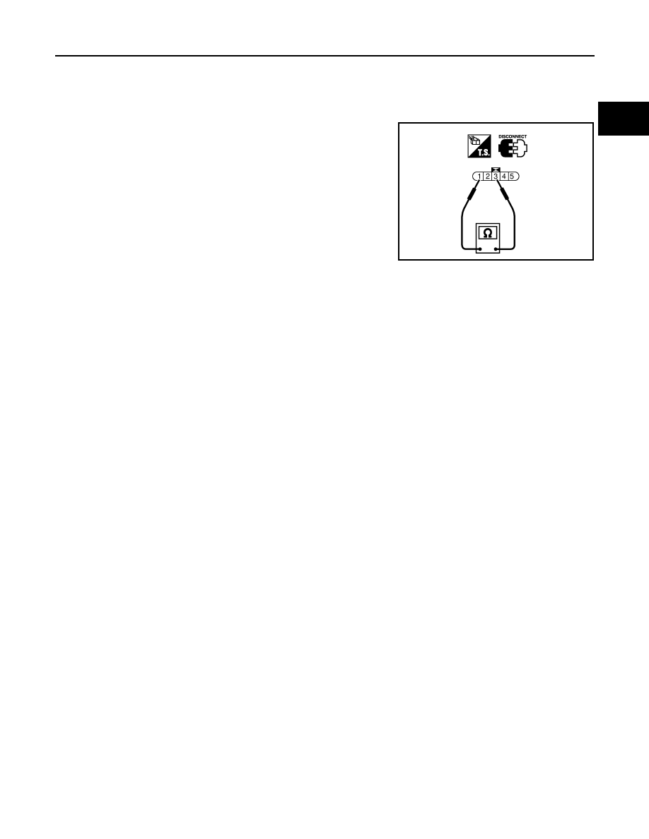
FUEL PUMP

1. Disconnect “fuel level sensor unit and fuel pump” harness connector.
2. Check resistance between “fuel level sensor unit and fuel pump”

terminals 1 and 3.

Resistance: Approximately 0.2 - 5.0

 [at 25

°

C (77

°

F)]

SEC918C

August 2012

2012 Pathfinder

EC-410

< DTC/CIRCUIT DIAGNOSIS >

[VQ40DE]

IGNITION SIGNAL

IGNITION SIGNAL

Component Description

INFOID:0000000007358375

IGNITION COIL & POWER TRANSISTOR

The ignition signal from the ECM is sent to and amplified by the power transistor. The power transistor turns

ON and OFF the ignition coil primary circuit. This ON/OFF operation induces the proper high voltage in the coil

secondary circuit.

Diagnosis Procedure

INFOID:0000000007358376

1.

CHECK ENGINE START

Turn ignition switch OFF, and restart engine.

Is engine running?

Yes or No

Yes (With CONSULT)>>GO TO 2.

Yes (Without CONSULT)>>GO TO 3.

No

>> GO TO 4.

2.

CHECK OVERALL FUNCTION


With CONSULT

1. Perform “POWER BALANCE” in “ACTIVE TEST” mode with CONSULT.

2. Make sure that each circuit produces a momentary engine speed drop.
OK or NG

OK

>>

INSPECTION END

NG

>> GO TO 10.

3.

CHECK OVERALL FUNCTION

 Without CONSULT

1. Let engine idle.

2. Read the voltage signal between ECM terminals 60, 61, 62, 79,

80, 81 and ground with an oscilloscope.

3. Verify that the oscilloscope screen shows the signal wave as

shown below.

NOTE:

The pulse cycle changes depending on rpm at idle.

OK or NG

OK

>>

INSPECTION END

NG

>> GO TO 10.

4.

CHECK IGNITION COIL POWER SUPPLY CIRCUIT-I

BBIA0561E

PBIB1186E

SEC986C

August 2012

2012 Pathfinder

IGNITION SIGNAL

EC-411

< DTC/CIRCUIT DIAGNOSIS >

[VQ40DE]

C

D

E

F

G

H

I

J

K

L

M

A

EC

N

P

O

1. Turn ignition switch OFF, wait at least 10 seconds and then turn it ON.

2. Check voltage between ECM terminals 119, 120 and ground

with CONSULT or tester.

OK or NG

OK

>> GO TO 5.

NG

>> Go to 

EC-94, "Diagnosis Procedure"

.

5.

CHECK IGNITION COIL POWER SUPPLY CIRCUIT-II

1. Turn ignition switch OFF.

2. Disconnect condenser-1 harness connector.

3. Turn ignition switch ON.

4. Check voltage between condenser-1 terminal 1 and ground with

CONSULT or tester.

OK or NG

OK

>> GO TO 8.

NG

>> GO TO 6.

6.

CHECK IGNITION COIL POWER SUPPLY CIRCUIT-III

1. Turn ignition switch OFF.

2. Disconnect IPDM E/R harness connector E119.

3. Check harness continuity between IPDM E/R terminal 3 and condenser-1 terminal 1.

Refer to Wiring Diagram.

4. Also check harness for short to ground and short to power.
OK or NG

OK

>> GO TO 17.

NG

>> GO TO 7.

7.

DETECT MALFUNCTIONING PART

Check the following.

• Harness connectors E2, F32

• Harness for open or short between condenser-1 and IPDM E/R

>> Repair open circuit or short to ground or short to power in harness or connectors.

Voltage: Battery voltage

MBIB0034E

BBIA0562E

Voltage: Battery voltage

PBIB0624E

Continuity should exist.

August 2012

2012 Pathfinder

EC-412

< DTC/CIRCUIT DIAGNOSIS >

[VQ40DE]

IGNITION SIGNAL

8.

CHECK CONDENSER-1 GROUND CIRCUIT FOR OPEN AND SHORT

1. Turn ignition switch OFF.

2. Check harness continuity between condenser-1 terminal 2 and ground.

Refer to Wiring Diagram.

3. Also check harness for short to power.
OK or NG

OK

>> GO TO 9.

NG

>> Repair open circuit or short to power in harness or connectors.

9.

CHECK CONDENSER-1

Refer to 

EC-413, "Component Inspection"

.

OK or NG

OK

>> GO TO 10.

NG

>> Replace condenser-1.

10.

CHECK IGNITION COIL POWER SUPPLY CIRCUIT-V

1. Turn ignition switch OFF.

2. Reconnect all harness connectors disconnected.

3. Disconnect ignition coil harness connector.

4. Turn ignition switch ON.

5. Check voltage between ignition coil terminal 3 and ground with

CONSULT or tester.

OK or NG

OK

>> GO TO 12.

NG

>> GO TO 11.

11.

DETECT MALFUNCTIONING PART

Check the following.

• Harness connectors F26, F225

• Harness for open or short between ignition coil and harness connector F32

>> Repair or replace harness or connectors.

12.

CHECK IGNITION COIL GROUND CIRCUIT FOR OPEN AND SHORT

1. Turn ignition switch OFF.

2. Check harness continuity between ignition coil terminal 2 and ground.

Refer to Wiring Diagram.

Continuity should exist.

Voltage: Battery voltage

BBIA0561E

PBIB0138E

Continuity should exist.

August 2012

2012 Pathfinder

IGNITION SIGNAL

EC-413

< DTC/CIRCUIT DIAGNOSIS >

[VQ40DE]

C

D

E

F

G

H

I

J

K

L

M

A

EC

N

P

O

3. Also check harness for short to power.
OK or NG

OK

>> GO TO 14.

NG

>> GO TO 13.

13.

DETECT MALFUNCTIONING PART

Check the following.

• Harness connectors F225, F26

• Harness for open or short between ignition coil and ground

>> Repair open circuit or short to power in harness or connectors.

14.

CHECK IGNITION COIL OUTPUT SIGNAL CIRCUIT FOR OPEN AND SHORT

1. Disconnect ECM harness connector.

2. Check harness continuity between ECM terminals 60, 61, 62, 79, 80, 81 and ignition coil terminal 1.

Refer to Wiring Diagram.

3. Also check harness for short to ground and short to power.
OK or NG

OK

>> GO TO 16.

NG

>> GO TO 15.

15.

DETECT MALFUNCTIONING PART

Check the following.

• Harness connectors F26, F225

• Harness for open or short between ignition coil and ECM

>> Repair open circuit or short to ground or short to power in harness or connectors.

16.

CHECK IGNITION COIL WITH POWER TRANSISTOR

Refer to 

EC-413, "Component Inspection"

.

OK or NG

OK

>> GO TO 17.

NG

>> Replace malfunctioning ignition coil with power transistor. Refer to 

EM-42, "Removal and Installa-

tion"

.

17.

CHECK INTERMITTENT INCIDENT

Refer to 

GI-37, "Intermittent Incident"

.

>>

INSPECTION END

Component Inspection

INFOID:0000000007358377

IGNITION COIL WITH POWER TRANSISTOR

CAUTION:

Do the following procedure in the place where ventilation is good without the combustible.

1. Turn ignition switch OFF.

2. Disconnect ignition coil harness connector.

Continuity should exist.

August 2012

2012 Pathfinder

EC-414

< DTC/CIRCUIT DIAGNOSIS >

[VQ40DE]

IGNITION SIGNAL

3. Check resistance between ignition coil terminals as follows.

4. If NG, Replace ignition coil with power transistor. Refer to 

EM-

42, "Removal and Installation"

.

If OK, go to next step.

5. Turn ignition switch OFF.

6. Reconnect all harness connectors disconnected.

7. Remove fuel pump fuse (No.48) in IPDM E/R to release fuel

pressure.

NOTE:

Do not use CONSULT to release fuel pressure, or fuel pressure

applies again during the following procedure.

8. Start engine.

9. After engine stalls, crank it two or three times to release all fuel

pressure.

10. Turn ignition switch OFF.

11. Remove ignition coil harness connectors to avoid the electrical

discharge from the ignition coils.

12. Remove ignition coil and spark plug of the cylinder to be

checked. Refer to 

EM-42, "Removal and Installation"

.

13. Crank engine for five seconds or more to remove combustion gas in the cylinder.

14. Connect spark plug and harness connector to ignition coil.

15. Fix ignition coil using a rope etc. with gap of 13 - 17 mm (0.52 -

0.66 in) between the edge of the spark plug and grounded metal

portion as shown in the figure.

16. Crank engine for about three seconds, and check whether spark

is generated between the spark plug and the grounded part.

CAUTION:

• Never place to the spark plug and the ignition coil within

50cm (19.7 in) each other. Be careful not to get an electri-

cal shock while checking, because the electrical dis-

charge voltage becomes 20 kV or more.

• It might cause to damage the ignition coil if the gap of more than 17 mm (0.66 in) is made.

NOTE:

When the gap is less than 13 mm (0.52 in), the spark might be generated even if the coil is mal-

functioning.

17. If NG, Replace ignition coil with power transistor. Refer to 

EM-42, "Removal and Installation"

.

CONDENSER-1

1. Turn ignition switch OFF.

2. Disconnect condenser-1 harness connector. For the condenser number, refer to 

EC-455, "Wiring Dia-

gram"

. For the condenser layout, refer to 

PG-39, "Harness Layout"

.

Terminal No. (Polarity)

Resistance 

 [at 25

°

C (77

°

F)]

1 and 2

Except 0 or 

1 and 3

Except 0

2 and 3

Spark should be generated.

PBIB0847E

BBIA0534E

JMBIA0066GB

August 2012

2012 Pathfinder

IGNITION SIGNAL

EC-415

< DTC/CIRCUIT DIAGNOSIS >

[VQ40DE]

C

D

E

F

G

H

I

J

K

L

M

A

EC

N

P

O

3. Check resistance between condenser-1 terminals 1 and 2.

Resistance

Above 1 M

 at 25

°

C (77

°

F)

PBIB0794E

August 2012

2012 Pathfinder

EC-416

< DTC/CIRCUIT DIAGNOSIS >

[VQ40DE]

ON BOARD REFUELING VAPOR RECOVERY (ORVR)

ON BOARD REFUELING VAPOR RECOVERY (ORVR)

System Description

INFOID:0000000007358378

From the beginning of refueling, the air and vapor inside the fuel tank go through refueling EVAP vapor cut

valve and EVAP/ORVR line to the EVAP canister. The vapor is absorbed by the EVAP canister and the air is

released to the atmosphere.

When the refueling has reached the full level of the fuel tank, the refueling EVAP vapor cut valve is closed and

refueling is stopped because of auto shut-off. The vapor which was absorbed by the EVAP canister is purged

during driving.

WARNING:

When conducting inspections below, Always observe the following:

• Put a “CAUTION: FLAMMABLE” sign in workshop.

• Never smoke while servicing fuel system. Keep open flames and sparks away from work area.

• Always furnish the workshop with a CO

2

 fire extinguisher.

CAUTION:

• Before removing fuel line parts, carry out the following procedures:

- Put drained fuel in an explosion-proof container and put lid on securely.

- Release fuel pressure from fuel line. Refer to 

EC-487, "Fuel Pressure Check"

.

- Disconnect battery negative cable.

• Always replace O-ring when the fuel gauge retainer is removed.

• Never kink or twist hose and tube when they are installed.

• Never tighten hose and clamps excessively to avoid damaging hoses.

• After installation, run engine and check for fuel leaks at connections.

• Never attempt to top off the fuel tank after the fuel pump nozzle shuts off automatically.

Continued refueling may cause fuel overflow, resulting in fuel spray and possibly a fire.

Diagnosis Procedure

INFOID:0000000007358379

SYMPTOM: FUEL ODOR FROM EVAP CANISTER IS STRONG.

1.

CHECK EVAP CANISTER

1. Remove EVAP canister with EVAP canister vent control valve and EVAP control system pressure sensor

attached. Refer to 

FL-16, "Removal and Installation"

.

2. Weigh the EVAP canister with EVAP canister vent control valve and EVAP control system pressure sensor

attached.

The weight should be less than 2.0 kg (4.4 lb).

OK or NG

OK

>> GO TO 2.

NG

>> GO TO 3.

PBIB1068E

August 2012

2012 Pathfinder


Content      ..     289      290      291      292     ..