Nissan Pathfinder (2012 year). Instruction - part 226


  Index      Instructions     Nissan Pathfinder (2012 year) - Service and Repair Instruction


Search            copyright infringement  


Content      ..     224      225      226      227     ..


Nissan Pathfinder (2012 year). Instruction - part 226


FRONT FINAL DRIVE

DLN-373

< UNIT DISASSEMBLY AND ASSEMBLY >

[FRONT FINAL DRIVE: R180A]

C

E

F

G

H

I

J

K

L

M

A

B

DLN

N

O

P

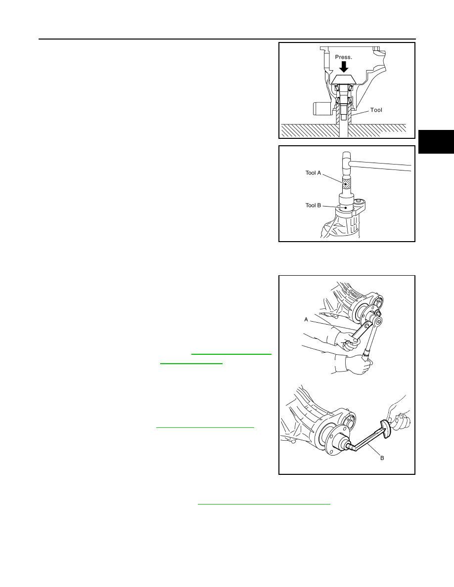
7. Press the drive pinion front bearing inner race to the drive pinion

as far as drive pinion lock nut can be tightened using Tool.

8. Apply multi-purpose grease to the lips and differential gear oil to

the circumference of the new front oil seal. Then drive the new

front oil seal in evenly until it becomes flush with the gear carrier

using Tools.

CAUTION:

• Do not reuse front oil seal.

• Do not incline the new front oil seal when installing.

• Apply multi-purpose grease to the lips and differential

gear oil to the circumference of the new front oil seal.

9. Install the companion flange to the drive pinion while aligning the matching marks.
10. Apply anti-corrosive oil to the threads of the drive pinion and the

seating surface of the new drive pinion lock nut. Then adjust the

drive pinion lock nut tightening torque using suitable tool (A),

and check the drive pinion bearing preload torque using Tool

(B).

CAUTION:

• Do not reuse drive pinion lock nut.

• Apply anti-corrosive oil to the threads of the drive pinion

and the seating surface of the new drive pinion lock nut.

• Adjust the drive pinion lock nut tightening torque to the

lower limit first. Do not exceed the drive pinion lock nut

specified torque. Refer to 

DLN-359, "Exploded View"

.

• If the drive pinion bearing preload torque exceeds the

specified value, replace collapsible spacer and tighten it

again to adjust. Do not loosen drive pinion lock nut to

adjust the drive pinion bearing preload torque.

• After adjustment, rotate drive pinion back and forth 2 to 3

times to check for unusual noise, rotation malfunction,

and other malfunctions.

11. Check companion flange runout. Refer to 

DLN-378, "Inspection and Adjustment"

.

12. Install the differential case assembly.

Differential Assembly

Tool number

: ST33200000 (J-26082)

PDIA0709E

Tool number

(A): ST30720000 (J-25405)
(B): ST27863000 ( — )

PDIA0717E

Tool number

(B): ST3127S000 (J-25765-A)

Drive pinion bearing 
preload torque

Refer to 

DLN-378, "Inspection 

and Adjustment"

WDIA0382E

August 2012

2012 Pathfinder

DLN-374

< UNIT DISASSEMBLY AND ASSEMBLY >

[FRONT FINAL DRIVE: R180A]

FRONT FINAL DRIVE

1. Install side gear thrust washers with the same thickness as the

ones installed prior to disassembly, or reinstall the old ones on

the side gears.

2. Install the side gears and side gear thrust washers into the dif-

ferential case.

3. Install the pinion mate thrust washers to the two pinion mate

gears. Then install the pinion mate gears with the pinion mate

thrust washers by aligning them in diagonally opposite positions

and rotating them into the differential case.

4. Install the pinion mate shaft and align the lock pin hole on the

pinion mate shaft with the lock pin hole on the differential case.

5. Measure the side gear end play. If necessary, select the appro-

priate side gear thrust washers. Refer to 

DLN-378, "Inspection

and Adjustment"

.

6. Drive a new lock pin into the pinion mate shaft until it is flush

with the differential case using suitable tool.

CAUTION:

Do not reuse lock pin.

7. Align the matching mark of the differential case with the mark of

the drive gear, then place the drive gear onto the differential

case.

SDIA0193J

SDIA2025E

SDIA0195J

SPD030

SDIA2593E

August 2012

2012 Pathfinder

FRONT FINAL DRIVE

DLN-375

< UNIT DISASSEMBLY AND ASSEMBLY >

[FRONT FINAL DRIVE: R180A]

C

E

F

G

H

I

J

K

L

M

A

B

DLN

N

O

P

8. Apply thread locking sealant into the threaded holes of the drive

gear and install the new drive gear bolts.

• Use Genuine High Strength Thread Locking Sealant or equiv-

alent. Refer to 

GI-14, "Recommended Chemical Products and

Sealants"

.

CAUTION:

Make sure the drive gear back and threaded holes are

clean.

9. Tighten the new drive gear bolts to the specified torque. Refer to

DLN-359, "Exploded View"

. After tightening the new drive gear

bolts to the specified torque, tighten an additional 34

°

 to 39

°

using Tool (A).

CAUTION:

• Always use Tool. Avoid tightening based on visual check

alone.

• Tighten new drive gear bolts in a crisscross pattern.

10. Press the new side bearing inner races to the differential case

using Tools.

CAUTION:

Do not reuse side bearing inner races.

11. Install housing spacer into gear carrier.
12. Apply differential gear oil to the side bearings, and install the dif-

ferential case assembly with the side bearing outer races into

the gear carrier.

CAUTION:

Do not reuse side bearing outer race when replacing side

bearing inner race (replace as a set).

SDIA2594E

Tool number

(A): KV10112100 (BT-8653-A)

AWBIA0722ZZ

Tool number

(A): ST33230000 (J-35867)
(B): ST33061000 (J-8107-2)

SPD353

SPD527

August 2012

2012 Pathfinder

DLN-376

< UNIT DISASSEMBLY AND ASSEMBLY >

[FRONT FINAL DRIVE: R180A]

FRONT FINAL DRIVE

13. Insert left and right original side bearing adjusting washers in

place between side bearings and gear carrier using Tool.

14. Install the side bearing caps with the matching marks aligned

and tighten the side bearing cap bolts to the specified torque.

Refer to 

DLN-359, "Exploded View"

.

15. Apply multi-purpose grease to the lips and differential gear oil to

the circumference of the new side oil seal. Then drive the new

side oil seal in evenly until it becomes flush with the gear carrier

using Tools.

CAUTION:

• Do not reuse side oil seal.

• Do not incline the new side oil seal when installing.

• Apply multi-purpose grease to the lips and differential

gear oil to the circumference of the new side oil seal.

16. Check and adjust tooth contact, backlash, drive gear runout and total preload torque. Refer to 

DLN-378,

"Inspection and Adjustment"

.

Recheck above items.

17. Apply a 3 mm (0.12 in) bead of sealant to the mating surface of

the carrier cover as shown.

• Use Genuine Silicone RTV or equivalent. Refer to 

GI-14,

"Recommended Chemical Products and Sealants"

.

CAUTION:

Remove any old sealant adhering to the mating surfaces.

Also remove any moisture, oil, or foreign material adhering

to the application and mating surfaces.

18. Install the carrier cover to the gear carrier. Tighten the bolts to

the specified torque. Refer to 

DLN-359, "Exploded View"

.

Differential side shaft

Tool number

: KV38100600 (J-25267)

PDIA0706E

PDIA0700E

Tool number

(A): ST30720000 (J-25405)
(B): ST27863000 ( — )

PDIA0711E

PDIA0712E

August 2012

2012 Pathfinder

FRONT FINAL DRIVE

DLN-377

< UNIT DISASSEMBLY AND ASSEMBLY >

[FRONT FINAL DRIVE: R180A]

C

E

F

G

H

I

J

K

L

M

A

B

DLN

N

O

P

1. Press differential side shaft bearing to differential side shaft.

CAUTION:

Do not reuse differential side shaft bearing.

2. Install snap ring (differential side shaft side).
3. Install differential side shaft assembly into gear carrier.
4. Install snap ring (hole side).

5. Apply multi-purpose grease to the lips and differential gear oil to

the circumference of the new side oil seal. Then drive the new

side oil seal in evenly until it becomes flush with the gear carrier

using Tools.

CAUTION:

• Do not reuse side oil seal.

• Do not incline the new side oil seal when installing.

• Apply multi-purpose grease to the lips and differential

gear oil to the circumference of the new side oil seal.

PDIA0719E

Tool number

(A): ST30720000 (J-25405)
(B): ST27863000 ( — )

PDIA0828E

August 2012

2012 Pathfinder

DLN-378

< SERVICE DATA AND SPECIFICATIONS (SDS) 

[FRONT FINAL DRIVE: R180A]

SERVICE DATA AND SPECIFICATIONS (SDS)

SERVICE DATA AND SPECIFICATIONS (SDS)

SERVICE DATA AND SPECIFICATIONS (SDS)

General Specification

INFOID:0000000007357619

Inspection and Adjustment

INFOID:0000000007357620

DRIVE GEAR RUNOUT

Unit: mm (in)

SIDE GEAR CLEARANCE

Unit: mm (in)

PRELOAD TORQUE

Unit: N·m (kg-m, in-lb)

BACKLASH

Unit: mm (in)

COMPANION FLANGE RUNOUT

Unit: mm (in)

SELECTIVE PARTS

Drive Pinion Height Adjusting Washer

Applied model

VQ40DE

Final drive model

R180A

Gear ratio

3.357

Number of teeth (Drive gear/Drive pinion)

47/14

Differential gear oil capacity (Approx.)

0.85 

 (1-3/4 US pt, 1-1/2 lmp pt)

Number of pinion gears

2

Drive pinion adjustment spacer type

Collapsible

Item

Runout limit

Drive gear back face

 0.08 (0.0031) or less

Item

Specification

Side gear back clearance (Clearance between side gear and differ-
ential case for adjusting side gear backlash)

0.1 (0.004) or less

(Each gear should rotate smoothly without excessive resistance 

during differential motion.)

Item

Specification

Drive pinion bearing preload torque

1.08 - 1.66 (0.11 - 0.16, 10 - 14)

Side bearing preload torque 

0.59 - 1.08 (0.06 - 0.11, 6 - 9)

Total preload torque
(Total preload torque = drive pinion bearing preload torque + side 
bearing preload torque).

1.67 - 2.74 (0.17 - 0.27, 15 - 24)

Item

Specification

Drive gear to drive pinion backlash

0.10 - 0.15 (0.0039 - 0.0059)

Item

Runout limit

Companion flange face

0.1 (0.004) or less

Companion flange inner side

0.1 (0.004) or less

August 2012

2012 Pathfinder

SERVICE DATA AND SPECIFICATIONS (SDS)

DLN-379

< SERVICE DATA AND SPECIFICATIONS (SDS) 

[FRONT FINAL DRIVE: R180A]

C

E

F

G

H

I

J

K

L

M

A

B

DLN

N

O

P

Unit: mm (in)

*: Always check with the Parts Department for the latest parts information.

Side Gear Thrust Washer

Unit: mm (in)

*: Always check with the Parts Department for the latest parts information.

Side Bearing Adjusting Washer

Unit: mm (in)

*: Always check with the Parts Department for the latest parts information.

Thickness Part 

number*

Thickness Part 

number*

3.09 (0.1217)
3.12 (0.1228)
3.15 (0.1240)
3.18 (0.1252)
3.21 (0.1264)
3.24 (0.1276)
3.27 (0.1287)
3.30 (0.1299)

3.33 (0.1311)

3.36 (0.1323)

38154 EA000
38154 EA001
38154 EA002
38154 EA003
38154 EA004
38154 EA005
38154 EA006
38154 EA007
38154 EA008
38154 EA009

3.39 (0.1335)
3.42 (0.1346)
3.45 (0.1358)
3.48 (0.1370)
3.51 (0.1382)
3.54 (0.1394)
3.57 (0.1406)
3.60 (0.1417)
3.63 (0.1429)
3.66 (0.1441)

38154 EA010

38154 EA011

38154 EA012
38154 EA013
38154 EA014
38154 EA015
38154 EA016
38154 EA017
38154 EA018
38154 EA019

Thickness Part 

number*

Thickness Part 

number*

0.75 (0.0295)
0.78 (0.0307)
0.81 (0.0319)
0.84 (0.0331)

38424 W2010

38424 W2011

38424 W2012
38424 W2013

0.87 (0.0343)
0.90 (0.0354)
0.93 (0.0366)
0.96 (0.0378)

38424 W2014
38424 W2015
38424 W2016
38424 W2017

Thickness

Part number*

Thickness

Part number*

1.95 (0.0768)
2.00 (0.0787)
2.05 (0.0807)
2.10 (0.0827)
2.15 (0.0846)
2.20 (0.0866)
2.25 (0.0886)
2.30 (0.0906)

38453 EA000
38453 EA001
38453 EA002
38453 EA003
38453 EA004
38453 EA005
38453 EA006
38453 EA007

2.35 (0.0925)
2.40 (0.0945)
2.45 (0.0965)
2.50 (0.0984)
2.55 (0.1004)
2.60 (0.1024)
2.65 (0.1043)

38453 EA008
38453 EA009
38453 EA010

38453 EA011

38453 EA012
38453 EA013
38453 EA014

August 2012

2012 Pathfinder

DLN-380

< PRECAUTION >

[FRONT FINAL DRIVE: M205]

PRECAUTIONS

PRECAUTION

PRECAUTIONS

Precaution for Supplemental Restraint System (SRS) "AIR BAG" and "SEAT BELT 
PRE-TENSIONER"

INFOID:0000000007357621

The Supplemental Restraint System such as “AIR BAG” and “SEAT BELT PRE-TENSIONER”, used along

with a front seat belt, helps to reduce the risk or severity of injury to the driver and front passenger for certain

types of collision. This system includes seat belt switch inputs and dual stage front air bag modules. The SRS

system uses the seat belt switches to determine the front air bag deployment, and may only deploy one front

air bag, depending on the severity of a collision and whether the front occupants are belted or unbelted.

Information necessary to service the system safely is included in the SR and SB section of this Service Man-

ual.

WARNING:

• To avoid rendering the SRS inoperative, which could increase the risk of personal injury or death in

the event of a collision which would result in air bag inflation, all maintenance must be performed by

an authorized NISSAN/INFINITI dealer.

• Improper maintenance, including incorrect removal and installation of the SRS, can lead to personal

injury caused by unintentional activation of the system. For removal of Spiral Cable and Air Bag

Module, see the SR section.

• Do not use electrical test equipment on any circuit related to the SRS unless instructed to in this

Service Instruction. SRS wiring harnesses can be identified by yellow and/or orange harnesses or har-

ness connectors.

PRECAUTIONS WHEN USING POWER TOOLS (AIR OR ELECTRIC) AND HAMMERS

WARNING:

• When working near the Airbag Diagnosis Sensor Unit or other Airbag System sensors with the Igni-

tion ON or engine running, DO NOT use air or electric power tools or strike near the sensor(s) with a

hammer. Heavy vibration could activate the sensor(s) and deploy the air bag(s), possibly causing

serious injury.

• When using air or electric power tools or hammers, always switch the Ignition OFF, disconnect the

battery, and wait at least 3 minutes before performing any service.

Precaution Necessary for Steering Wheel Rotation After Battery Disconnect

INFOID:0000000007357622

NOTE:

• This Procedure is applied only to models with Intelligent Key system and NATS (NISSAN ANTI-THEFT SYS-

TEM).

• Remove and install all control units after disconnecting both battery cables with the ignition knob in the

LOCK

 position.

• Always use CONSULT to perform self-diagnosis as a part of each function inspection after finishing work. If

DTC is detected, perform trouble diagnosis according to self-diagnostic results.

For models equipped with the Intelligent Key system and NATS, an electrically controlled steering lock mech-

anism is adopted on the key cylinder.

For this reason, if the battery is disconnected or if the battery is discharged, the steering wheel will lock and

steering wheel rotation will become impossible.

If steering wheel rotation is required when battery power is interrupted, follow the procedure below before

starting the repair operation.

OPERATION PROCEDURE

1. Connect both battery cables.

NOTE:

Supply power using jumper cables if battery is discharged.

2. Use the Intelligent Key or mechanical key to turn the ignition switch to the 

ACC

 position. At this time, the

steering lock will be released.

3. Disconnect both battery cables. The steering lock will remain released and the steering wheel can be

rotated.

4. Perform the necessary repair operation.

August 2012

2012 Pathfinder


Content      ..     224      225      226      227     ..