Nissan Pathfinder (2011 year). Instruction - part 554
 

  Index      Instructions     Nissan Pathfinder (2011 year) - Service and Repair Instruction


Search            copyright infringement  


Content      ..     552      553      554      555     ..


Nissan Pathfinder (2011 year). Instruction - part 554


POWER SUPPLY AND GROUND CIRCUIT

SEC-139

< DTC/CIRCUIT DIAGNOSIS >

[WITHOUT INTELLIGENT KEY SYSTEM]

C

D

E

F

G

H

I

J

L

M

A

B

SEC

N

O

P

POWER SUPPLY AND GROUND CIRCUIT

BCM
BCM : Diagnosis Procedure

INFOID:0000000006767002

Regarding Wiring Diagram information, refer to 

BCS-48, "Wiring Diagram"

.

1.

 CHECK FUSES AND FUSIBLE LINK

Check that the following fuses and fusible link are not blown.

Is the fuse blown?

YES

>> Replace the blown fuse or fusible link after repairing the affected circuit.

NO

>> GO TO 2

2.

 CHECK POWER SUPPLY CIRCUIT

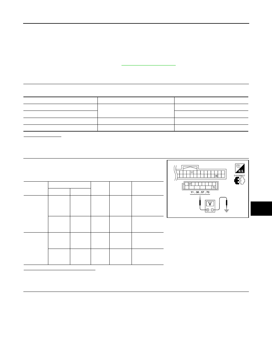
1. Turn ignition switch OFF.

2. Disconnect BCM.

3. Check voltage between BCM harness connector and ground.

Is the measurement value normal?

YES

>> GO TO 3

NO

>> Repair or replace harness.

3.

 CHECK GROUND CIRCUIT

Terminal No.

Signal name

Fuses and fusible link No.

57

Battery power supply

21 (10A)

70

G (50A)

11

Ignition ACC or ON

4 (10A)

38

Ignition ON or START

1 (10A)

Connector

Terminals 

Power

source

Condition

Voltage (V) (Ap-

prox.)

(+)

(-)

M18

11

Ground

ACC 

power 

supply

Ignition 

switch 

ACC or 

ON

Battery voltage

38

Ground

Ignition 

power 

supply

Ignition 

switch ON 

or START

Battery voltage

M20

57

Ground

Battery 

power 

supply

Ignition 

switch 

OFF

Battery voltage

70

Ground

Battery 

power 

supply

Ignition 

switch 

OFF

Battery voltage

LIIA2415E

2011 Pathfinder

SEC-140

< DTC/CIRCUIT DIAGNOSIS >

[WITHOUT INTELLIGENT KEY SYSTEM]

POWER SUPPLY AND GROUND CIRCUIT

Check continuity between BCM harness connector and ground.

Does continuity exist?

YES

>> Inspection End.

NO

>> Repair or replace harness.

BCM

Ground

Continuity

Connector

Terminal

M20

67

Yes

LIIA0915E

2011 Pathfinder

KEY CYLINDER SWITCH

SEC-141

< DTC/CIRCUIT DIAGNOSIS >

[WITHOUT INTELLIGENT KEY SYSTEM]

C

D

E

F

G

H

I

J

L

M

A

B

SEC

N

O

P

KEY CYLINDER SWITCH

Description

INFOID:0000000006246326

The main power window and door lock/unlock switch detects condition of the door key cylinder switch and

transmits to BCM as the LOCK or UNLOCK signal. 

Component Function Check

INFOID:0000000006246327

1.

CHECK DOOR KEY CYLINDER SWITCH INPUT SIGNAL

Check "KEY CYL LK-SW" AND "KEY CYL UN-SW" in DATA MONITOR mode for “POWER DOOR LOCK

SYSTEM” with CONSULT-III.

Is the inspection result normal?

YES

>> Key cylinder switch is OK.

NO

>> Refer to 

SEC-141, "Diagnosis Procedure"

.

Diagnosis Procedure

INFOID:0000000006246328

Regarding Wiring Diagram information, refer to 

SEC-166, "Wiring Diagram"

.

1.

CHECK DOOR KEY CYLINDER SWITCH LH

With CONSULT-III

Check front door lock assembly LH (key cylinder switch) ("KEY CYL LK-SW") and ("KEY CYL UN-SW) in

DATA MONITOR mode with CONSULT–III.

• When key inserted in left front key cylinder is turned to LOCK:

• When key inserted in left front key cylinder is turned to UNLOCK:

Without CONSULT-III

1. Turn ignition switch OFF.

2. Check voltage between main power window and door lock/

unlock switch connector D7 terminals 4, 6 and ground.

Is the inspection result normal?

Monitor item

Condition

KEY CYL LK-SW

Lock

: ON

Neutral / Unlock

: OFF

KEY CYL UN-SW

Unlock

: ON

Neutral / Lock

: OFF

KEY CYL LK-SW

: ON

KEY CYL UN-SW

: ON

Connector

Terminals

Condition of left front key cylinder

Voltage (V)

(Approx.)

(+)

(–)

D7

4

Ground

Neutral/Unlock

5

Lock

0

6

Neutral/Lock

5

Unlock

0

LIIA0566E

2011 Pathfinder

SEC-142

< DTC/CIRCUIT DIAGNOSIS >

[WITHOUT INTELLIGENT KEY SYSTEM]

KEY CYLINDER SWITCH

YES

>> Key cylinder switch signal is OK.

NO

>> GO TO 2

2.

CHECK DOOR KEY CYLINDER SWITCH LH GROUND HARNESS

1. Turn ignition switch OFF.

2. Disconnect front door lock assembly LH (key cylinder switch).

3. Check continuity between front door lock assembly LH (key cyl-

inder switch) connector D14 terminal 4 and body ground.

Is the inspection result normal?

YES

>> GO TO 3

NO

>> Repair or replace harness.

3.

CHECK DOOR KEY CYLINDER SWITCH LH

Check continuity between front door lock assembly LH (key cylinder

switch) terminals.

Is the inspection result normal?

YES

>> GO TO 4

NO

>> Replace front door lock assembly LH (key cylinder switch). Refer to 

DLK-324, "Removal and

Installation"

.

4.

CHECK DOOR KEY CYLINDER HARNESS

Check continuity between main power window and door lock/unlock switch connector D7 (

A) terminals 4, 6 and front door lock assembly LH (key cylinder

switch) connector D14 (B) terminals 3, 5 and body ground. 

Is the inspection result normal?

YES

>> Replace main power window and door lock/unlock switch.

NO

>> Repair or replace harness.

Connector

Terminals

Continuity

D14

4 – Ground

Yes

ALKIA1186ZZ

Terminals

Condition

Continuity

3 – 4

Key is turned to LOCK or neutral.

No

Key is turned to UNLOCK.

Yes

4 – 5

Key is turned to UNLOCK or neutral.

No

Key is turned to LOCK.

Yes

ALKIA1183ZZ

Connector

Terminals

Connector

Terminals

Continuity

A: Main 

power win-

dow and 

door lock/

unlock 

switch

4

B:  Front 

door lock 

assembly 

LH (key 
cylinder 

switch)

5

Yes

6

3

Yes

4, 6

Ground

No

ALKIA1184ZZ

2011 Pathfinder

GLASS HATCH AJAR SWITCH

SEC-143

< DTC/CIRCUIT DIAGNOSIS >

[WITHOUT INTELLIGENT KEY SYSTEM]

C

D

E

F

G

H

I

J

L

M

A

B

SEC

N

O

P

GLASS HATCH AJAR SWITCH

Description

INFOID:0000000006246329

Detects glass hatch open/close condition.

Component Function Check

INFOID:0000000006246330

1.

CHECK FUNCTION

With CONSULT-III

Check glass hatch switch in data monitor mode with CONSULT-III.

Is the inspection result normal?

YES

>> Glass hatch switch is OK.

NO

>> Refer to 

SEC-143, "Diagnosis Procedure"

.

Diagnosis Procedure

INFOID:0000000006246331

Regarding Wiring Diagram information, refer to 

SEC-166, "Wiring Diagram"

.

1.

CHECK GLASS HATCH AJAR SWITCH INPUT SIGNAL

With CONSULT-III

Check glass hatch ajar switch "GLASS HATCH SW" in DATA MONITOR mode with CONSULT–III.

• When glass hatch is open:

• When glass hatch is closed:

Without CONSULT-III

1. Turn ignition switch OFF.

2. Check voltage between BCM connector M19 terminals 42 and ground.

Is the inspection result normal?

YES

>> Glass hatch ajar switch circuit is OK.

NO

>> GO TO 2

2.

CHECK GLASS HATCH AJAR SWITCH CIRCUIT

1. Disconnect glass hatch ajar switch and BCM.

2. Check continuity between BCM connector M19 (A) terminal 42 and glass hatch ajar switch connector

D503 (B) terminal 1.

Monitor item

Condition

GLASS HATCH SW

CLOSE 

 OPEN: OFF 

 ON

GLASS HATCH SW

:ON

GLASS HATCH SW

:OFF

Connector

Item

Terminals

Condition

Voltage (V)

(Approx.)

( + )

( – )

M19

BCM

42

Ground

Open

Closed

0

Battery voltage

ALKIA1708ZZ

2011 Pathfinder

SEC-144

< DTC/CIRCUIT DIAGNOSIS >

[WITHOUT INTELLIGENT KEY SYSTEM]

GLASS HATCH AJAR SWITCH

3. Check continuity between BCM connector M19 (A) terminal 42

and ground.

Is the inspection result normal?

YES

>> GO TO 3

NO

>> Repair or replace harness.

3.

CHECK GLASS HATCH AJAR SWITCH

Check continuity between glass hatch ajar switch connector terminal 1 and ground.

Is the inspection result normal?

YES

>> Refer to 

GI-37, "Intermittent Incident"

.

NO

>> Replace glass hatch ajar switch.

42 - 1

:Continuity should exist

42 - Ground

:Continuity should not exist

ALKIA1709ZZ

Terminals

Condition

Continuity

Glass hatch ajar 

switch 

1 – Ground

Open

Yes

Closed

No

ALKIA0668ZZ

2011 Pathfinder

HORN FUNCTION

SEC-145

< DTC/CIRCUIT DIAGNOSIS >

[WITHOUT INTELLIGENT KEY SYSTEM]

C

D

E

F

G

H

I

J

L

M

A

B

SEC

N

O

P

HORN FUNCTION

Symptom Table

INFOID:0000000006246332

HAZARD AND HORN REMINDER FUNCTION MALFUNCTION

NOTE:

• Before performing the diagnosis in the following table, check “Work flow”. Refer to 

SEC-115, "Work Flow"

.

• If the following symptoms” are detected, check systems shown in the “Diagnosis/service procedure” column

in this order.

Conditions of Vehicle (Operating Conditions)

• “ANSWER BACK FUNCTION” is ON when setting on CONSULT-III.

• Ignition switch is in OFF position.

• All doors are closed.

Symptom

Diagnosis/service procedure

Reference 

page

Hazard reminder does not operate by key fob.
(Horn reminder operate.)

1.

Check “HAZARD ANSWER BACK” setting in “WORK 
SUPPORT”.

BCS-19

2. Check hazard function.

EXL-4

3. Check keyfob battery inspection.

DLK-253

Horn reminder does not operate by key fob.
(Hazard reminder operate.)

1.

Check “HORN WITH KEYLESS LOCK” setting in 
“WORK SUPPORT”.

BCS-19

2. Check horn function.

SEC-166

3. Check Intermittent Incident.

GI-37

2011 Pathfinder

SEC-146

< DTC/CIRCUIT DIAGNOSIS >

[WITHOUT INTELLIGENT KEY SYSTEM]

VEHICLE SECURITY INDICATOR

VEHICLE SECURITY INDICATOR

Description

INFOID:0000000006246333

• Vehicle security indicator is built in combination meter.

• NATS (Nissan Anti-Theft System) and vehicle security system conditions are indicated by blink or illumina-

tion of vehicle security indicator.

Component Function Check

INFOID:0000000006246334

1.

CHECK FUNCTION

1. Perform “THEFT IND” in the “Active Test” mode with CONSULT-III.

2. Check vehicle security indicator operation.

Is the inspection result normal?

YES

>> Inspection End.

NO

>> Refer to 

SEC-146, "Diagnosis Procedure"

.

Diagnosis Procedure

INFOID:0000000006246335

Regarding Wiring Diagram information, refer to 

SEC-176, "Wiring Diagram - Without Intelligent Key System"

.

1.

SECURITY INDICATOR LAMP ACTIVE TEST

With CONSULT-III

Check "THEFT IND” in "ACTIVE TEST" mode with CONSULT-III.

Without CONSULT-III

1. Disconnect BCM.

2. Turn ignition switch ON.

3. Check voltage between BCM harness connector M18 terminal

23 and ground.

Is the inspection result normal?

YES

>> Security indicator lamp is OK.

NO

>> GO TO 2

2.

SECURITY INDICATOR LAMP CHECK

Check security indicator lamp condition.
Is the inspection result normal?

YES

>> GO TO 3

NO

>> Replace combination meter.  Refer to 

MWI-88, "Removal and Installation"

.

3.

CHECK HARNESS CONTINUITY

1. Turn ignition switch OFF.

2. Disconnect BCM and security indicator lamp connector.

Test item

Description

THEFT IND

ON

Vehicle security indicator

ON

OFF

OFF

Connector

Terminals

Condition

Voltage (V)

(Approx.)

(+)

(-)

M18

23

Ground

ON

0

OFF

Battery voltage

LIIA0523E

2011 Pathfinder


Content      ..     552      553      554      555     ..