Nissan Pathfinder (2011 year). Instruction - part 470


  Index      Instructions     Nissan Pathfinder (2011 year) - Service and Repair Instruction


Search            copyright infringement  


Content      ..     468      469      470      471     ..


Nissan Pathfinder (2011 year). Instruction - part 470


INT-24

< REMOVAL AND INSTALLATION >

LUGGAGE FLOOR TRIM

LUGGAGE FLOOR TRIM

Component

INFOID:0000000006243565
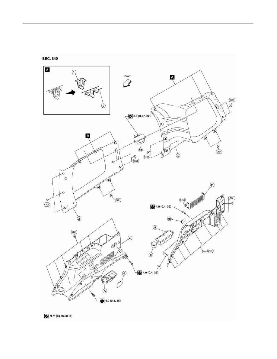
Luggage Trim - Side

AWJIA0556GB

1.

Metal clip

2.

Garnish

3.

Luggage side upper finisher RH

4.

Luggage side lower finisher RH

5.

Cup holder and tray

6.

Access cover

7.

Luggage side lower finisher LH

8.

Cup holder

9.

Storage bin

2011 Pathfinder

LUGGAGE FLOOR TRIM

INT-25

< REMOVAL AND INSTALLATION >

C

D

E

F

G

H

I

K

L

M

A

B

INT

N

O

P

Luggage Trim - Floor

Removal and Installation

INFOID:0000000006243566

REMOVAL

1. Remove the 2nd and 3rd row seat belts. Refer to 

SB-6, "Removal and Installation of Rear Seat Belt"

 and

SB-8, "Removal and Installation of Third Row Seat Belt"

.

2. Remove the third row seat belt buckles. Refer to 

SB-8, "Removal and Installation of Third Row Seat Belt"

.

3. Remove the rear door kick plates. refer to 

INT-18

.

4. Remove the back door kick plate.

10. Access cover

11. Side cargo net

12. Luggage side upper finisher LH

13. Coat hook

AWJIA0057GB

1.

Floor storage bin

2.

Flipper panel

3.

Storage tray

4.

Luggage floor board latch

5.

Luggage floor board

6.

Tailgate kick plate

7.

Cargo net

A.

Clip

B.

Clip

Front

2011 Pathfinder

INT-26

< REMOVAL AND INSTALLATION >

LUGGAGE FLOOR TRIM

5. Disconnect the door open/close link. Refer to 

DLK-205, "Component Structure"

.

6. Remove the cargo net hooks.
7. Remove the LH and RH luggage side lower finishers.

• Disconnect the power point on the RH side.

8. Remove the LH and RH coat hooks.
9. Remove the LH and RH luggage side upper finishers.
10. Remove the cargo net hooks LH/RH.
11. Remove the luggage floor board.
12. Remove the flipper panel.
13. Remove the storage tray.
14. Remove the floor storage bin.

INSTALLATION

Installation is in the reverse order of removal.

2011 Pathfinder

BACK DOOR TRIM

INT-27

< REMOVAL AND INSTALLATION >

C

D

E

F

G

H

I

K

L

M

A

B

INT

N

O

P

BACK DOOR TRIM

Removal and Installation

INFOID:0000000006243567

REMOVAL

1. Open the back door glass.
2. Disconnect the gas spring LH and RH from the back door (through window garnish).
3. Open the back door, release the clips and remove the back door window garnish.
4. Remove the screw and the back door handle.
5. Release the clips and remove the back door finisher assembly.

INSTALLATION

Installation is in the reverse order of removal.

1.

Back door window garnish

2.

Back door finisher

3.

Back door handle bracket

4.

Back door handle

5.

First aid kit strap

6.

First aid kit

Vehicle front

WIIA0725E

2011 Pathfinder

IP-1

BODY INTERIOR

C

D

E

F

G

H

I

K

L

M

SECTION 

IP

A

B

IP

N

O

P

CONTENTS

INSTRUMENT PANEL

PRECAUTION ...............................................

2

PRECAUTIONS ...................................................

2

Precaution for Supplemental Restraint System 
(SRS) "AIR BAG" and "SEAT BELT PRE-TEN-
SIONER" .................................................................
..

2

Precaution Necessary for Steering Wheel Rota-
tion After Battery Disconnect ...................................
..

2

Precaution for Work  ..................................................

3

PREPARATION ............................................

4

PREPARATION ...................................................

4

Special Service Tool  .................................................

4

Commercial Service Tool  ..........................................

4

SYMPTOM DIAGNOSIS  ...............................

5

SQUEAK AND RATTLE TROUBLE DIAG-
NOSES ................................................................

5

Work Flow  .................................................................

5

Generic Squeak and Rattle Troubleshooting  ............

7

Diagnostic Worksheet  ...............................................

9

REMOVAL AND INSTALLATION ...............

11

INSTRUMENT PANEL ASSEMBLY  ..................

11

Exploded View  ........................................................

11

Removal and Installation .........................................

12

CLUSTER LID A .................................................

13

Removal and Installation .........................................

13

INSTRUMENT LOWER PANEL LH ..................

14

Removal and Installation  .........................................

14

CLUSTER LID C  ...............................................

15

Removal and Installation  .........................................

15

CLUSTER LID D  ...............................................

17

Removal and Installation  .........................................

17

UPPER GLOVE BOX ........................................

18

Removal and Installation  .........................................

18

INSTRUMENT LOWER PANEL RH AND 
GLOVE BOX  .....................................................

19

Removal and Installation  .........................................

19

A/T FINISHER  ...................................................

20

Removal and Installation  .........................................

20

CENTER CONSOLE  .........................................

21

Removal and Installation  .........................................

21

UNIT DISASSEMBLY AND ASSEMBLY  ....

22

CENTER CONSOLE ASSEMBLY  ....................

22

Disassembly and Assembly .....................................

22

INSTRUMENT LOWER PANEL RH AND 
GLOVE BOX  .....................................................

24

Exploded View .........................................................

24

Disassembly and Assembly .....................................

24

2011 Pathfinder

IP-2

< PRECAUTION >

PRECAUTIONS

PRECAUTION

PRECAUTIONS

Precaution for Supplemental Restraint System (SRS) "AIR BAG" and "SEAT BELT 
PRE-TENSIONER"

INFOID:0000000006247939

The Supplemental Restraint System such as “AIR BAG” and “SEAT BELT PRE-TENSIONER”, used along

with a front seat belt, helps to reduce the risk or severity of injury to the driver and front passenger for certain

types of collision. This system includes seat belt switch inputs and dual stage front air bag modules. The SRS

system uses the seat belt switches to determine the front air bag deployment, and may only deploy one front

air bag, depending on the severity of a collision and whether the front occupants are belted or unbelted.

Information necessary to service the system safely is included in the SR and SB section of this Service Man-

ual.

WARNING:

• To avoid rendering the SRS inoperative, which could increase the risk of personal injury or death in

the event of a collision which would result in air bag inflation, all maintenance must be performed by

an authorized NISSAN/INFINITI dealer.

• Improper maintenance, including incorrect removal and installation of the SRS, can lead to personal

injury caused by unintentional activation of the system. For removal of Spiral Cable and Air Bag

Module, see the SR section.

• Do not use electrical test equipment on any circuit related to the SRS unless instructed to in this

Service Instruction. SRS wiring harnesses can be identified by yellow and/or orange harnesses or har-

ness connectors.

PRECAUTIONS WHEN USING POWER TOOLS (AIR OR ELECTRIC) AND HAMMERS

WARNING:

• When working near the Airbag Diagnosis Sensor Unit or other Airbag System sensors with the Igni-

tion ON or engine running, DO NOT use air or electric power tools or strike near the sensor(s) with a

hammer. Heavy vibration could activate the sensor(s) and deploy the air bag(s), possibly causing

serious injury.

• When using air or electric power tools or hammers, always switch the Ignition OFF, disconnect the

battery, and wait at least 3 minutes before performing any service.

Precaution Necessary for Steering Wheel Rotation After Battery Disconnect

INFOID:0000000006247940

NOTE:

• This Procedure is applied only to models with Intelligent Key system and NATS (NISSAN ANTI-THEFT SYS-

TEM).

• Remove and install all control units after disconnecting both battery cables with the ignition knob in the

LOCK

 position.

• Always use CONSULT-III to perform self-diagnosis as a part of each function inspection after finishing work.

If DTC is detected, perform trouble diagnosis according to self-diagnostic results.

For models equipped with the Intelligent Key system and NATS, an electrically controlled steering lock mech-

anism is adopted on the key cylinder.

For this reason, if the battery is disconnected or if the battery is discharged, the steering wheel will lock and

steering wheel rotation will become impossible.

If steering wheel rotation is required when battery power is interrupted, follow the procedure below before

starting the repair operation.

OPERATION PROCEDURE

1. Connect both battery cables.

NOTE:

Supply power using jumper cables if battery is discharged.

2. Use the Intelligent Key or mechanical key to turn the ignition switch to the 

ACC

 position. At this time, the

steering lock will be released.

3. Disconnect both battery cables. The steering lock will remain released and the steering wheel can be

rotated.

4. Perform the necessary repair operation.

2011 Pathfinder

PRECAUTIONS

IP-3

< PRECAUTION >

C

D

E

F

G

H

I

K

L

M

A

B

IP

N

O

P

5. When the repair work is completed, return the ignition switch to the 

LOCK

 position before connecting

the battery cables. (At this time, the steering lock mechanism will engage.)

6. Perform a self-diagnosis check of all control units using CONSULT-III. 

Precaution for Work

INFOID:0000000006826738

• When removing or disassembling each component, be careful not to damage or deform it. If a component

may be subject to interference, be sure to protect it with a shop cloth.

• When removing (disengaging) components with a screwdriver or similar tool, be sure to wrap the component

with a shop cloth or vinyl tape to protect it.

• Protect the removed parts with a shop cloth and prevent them from being dropped.

• Replace a deformed or damaged clip.

• If a part is specified as a non-reusable part, always replace it with new one.

• Be sure to tighten bolts and nuts securely to the specified torque.

• After installation is complete, be sure to check that each part works properly.

• Follow the steps below to clean components.

- Water soluble dirt: Dip a soft cloth into lukewarm water, and wring the water out of the cloth to wipe the dirty

area.

Then rub with a soft and dry cloth.

- Oily dirt: Dip a soft cloth into lukewarm water with mild detergent (concentration: within 2 to 3%), and wipe

the dirty area.

Then dip a cloth into fresh water, and wring the water out of the cloth to wipe the detergent off. Then rub with

a soft and dry cloth.

• Do not use organic solvent such as thinner, benzene, alcohol, or gasoline.

• For genuine leather seats, use a genuine leather seat cleaner.

2011 Pathfinder

IP-4

< PREPARATION >

PREPARATION

PREPARATION

PREPARATION

Special Service Tool

INFOID:0000000006247941

The actual shapes of Kent-Moore tools may differ from those of special service tools illustrated here.

Commercial Service Tool

INFOID:0000000006247942

Tool number
(Kent-Moore No.)
Tool name

Description

(J-39570)
Chassis ear

Locating the noise

(J-43980)
NISSAN Squeak and Rattle kit

Repairing the cause of noise

(J-46534)
Trim tool set

For removing trim

SBT839

SBT840

AWJIA0483ZZ

(Kent-Moore No.)
Tool name

Description

(J-39565)
Engine ear

Locating the noise

Power tool

Loosening bolts, screws and nuts.

SIIA0995E

PIIB1407E

2011 Pathfinder


Content      ..     468      469      470      471     ..