Nissan Pathfinder (2011 year). Instruction - part 384


  Index      Instructions     Nissan Pathfinder (2011 year) - Service and Repair Instruction


Search            copyright infringement  


Content      ..     382      383      384      385     ..


Nissan Pathfinder (2011 year). Instruction - part 384


FUEL INJECTOR AND FUEL TUBE

EM-183

< REMOVAL AND INSTALLATION >

[VK56DE]

C

D

E

F

G

H

I

J

K

L

M

A

EM

N

P

O

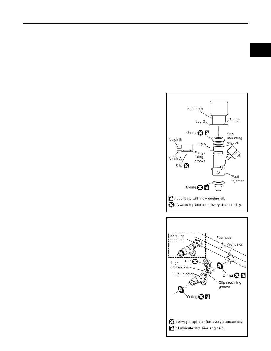
• Upper and lower O-rings are different colors. 

• Handle O-ring with bare hands. Never wear gloves.

• Lubricate new O-ring with new engine oil.

• Do not clean O-ring with solvent.

• Make sure that O-ring and its mating part are free of foreign material.

• When installing O-ring, be careful not to scratch it with tool or fingernails. Also be careful not to

twist or stretch O-ring. 

• If O-ring was stretched while it was being attached, do not insert it quickly into fuel tube.

• Insert O-ring straight into fuel tube. Do not angle or twist it.

3. Install the fuel injector to the fuel tube.
a. Insert new clip into clip mounting groove on the fuel injector.

• Insert clip so that lug 

A

 of fuel injector matches notch 

A

 of

the clip.

CAUTION:

• Do not reuse clip. Replace it with a new one.

• Do not allow the clip to interfere with the O-ring. If inter-

ference occurs, replace the O-ring.

b. Insert the fuel injector into the fuel tube with the clip attached.

• Insert it while matching it to the axial center.

• Insert fuel injector so that lug 

B

 of fuel tube matches notch

B

 of the clip.

• Make sure that the fuel tube flange is securely seated in the

flange fixing groove on the clip.

c. Make sure that installation is complete by checking that the fuel

injector does not rotate or come off.

• Make sure that the protrusions of the fuel injectors are aligned

with the cutouts of the clips after installation.

Fuel tube side

: Blue

Nozzle side

: Brown

KBIA2507E

KBIA2506E

2011 Pathfinder

EM-184

< REMOVAL AND INSTALLATION >

[VK56DE]

FUEL INJECTOR AND FUEL TUBE

4. Install the fuel tube and fuel injector assembly to the intake manifold.

CAUTION:

Do not let the tip of the injector nozzle come in contact with other parts.

• Tighten fuel tube assembly bolts 

a

 to 

b

 in illustration in two

steps.

5. Install the fuel hose assembly.

• Insert connectors straight, making sure that the axis is lined up with fuel tube side to prevent O-ring from

being damaged.

• Tighten bolts evenly in several steps.

• Make sure that there is no gap between the flange and fuel tube after tightening the bolts.

CAUTION:

• Handle O-ring with bare hands. Do not wear gloves.

• Lubricate O-ring with new engine oil.

• Do not clean O-ring with solvent.

• Make sure that O-ring and its mating part are free of foreign material.

• When installing O-ring, be careful not to scratch it with tool or fingernails. Also be careful not to

twist or stretch O-ring. 

• If O-ring was stretched while it was being attached, do not insert it quickly into fuel tube.

• Insert new O-ring straight into fuel tube. Do not twist it.

• Do not reuse O-rings.

6. Installation of the remaining components is in the reverse order of removal.

INSPECTION AFTER INSTALLATION

After installing the fuel tubes, make sure there are no fuel leaks at the connections using the following steps.
1. Apply fuel pressure to the fuel lines by turning ignition switch ON (with engine stopped). Then check for

fuel leaks at the connections.

2. Start the engine and rev it up and check for fuel leaks at the connections.

WARNING:

Do not touch the engine immediately after stopping, as engine becomes extremely hot.

NOTE:

Use mirrors for checking on hidden points.

1st step

: 12.8 N·m (1.3 kg-m, 9 ft-lb)

2nd step

: 24.5 N·m (2.5 kg-m, 18 ft-lb)

KBIA2474E

2011 Pathfinder

INTAKE VALVE TIMING CONTROL

EM-185

< REMOVAL AND INSTALLATION >

[VK56DE]

C

D

E

F

G

H

I

J

K

L

M

A

EM

N

P

O

INTAKE VALVE TIMING CONTROL

Intake Valve Timing Control Solenoid Valve (Bank1) (LH)

INFOID:0000000006627318

REMOVAL

1. Remove air duct and resonator assembly. Refer to 

EM-165, "Removal and Installation"

.

2. Remove drive belt. Refer to 

EM-153, "Removal and Installation"

.

3. Disconnect Intake valve timing control solenoid valve connector (Bank1) (LH).
4. Remove Intake valve timing control solenoid valve (Bank1) (LH)

(2) and O-ring (3) from Intake valve timing control solenoid valve

cover (Bank1) (LH) (1).

CAUTION:

Do not reuse O-rings.

INSTALLATION

Installation is in the reverse order of removal.

CAUTION:

• Do not reuse O-rings.

• Replace the O-ring for the intake valve timing control solenoid valve with a new one. 

• Lubricate O-ring with engine oil before installing.

Intake Valve Timing Control Solenoid Valve (Bank 2) (RH)

INFOID:0000000006627319

REMOVAL

1. Remove drive belt. Refer to 

EM-153, "Removal and Installation"

.

2. Disconnect Intake valve timing control solenoid valve connector (Bank 2) (RH).
3. Remove Intake valve timing control solenoid valve (Bank 2)

(RH) (3) and O-ring (2) from Intake valve timing control solenoid

valve cover (Bank 2) (RH) (1).

CAUTION:

Do not reuse O-rings.

INSTALLATION

Installation is in the reverse order of removal.

CAUTION:

• Do not reuse O-rings.

• Replace the O-ring for the intake valve timing control solenoid valve with a new one. 

• Lubricate O-ring with engine oil before installing.

AWBIA0145ZZ

Intake valve timing control 
solenoid valve bolt

: 9.0 N·m (0.92 kg-m, 80 in-lb)

AWBIA0144ZZ

Intake valve timing control 
solenoid valve bolt

: 9.0 N·m (0.92 kg-m, 80 in-lb)

2011 Pathfinder

EM-186

< REMOVAL AND INSTALLATION >

[VK56DE]

INTAKE VALVE TIMING CONTROL

Intake Valve Timing Control Position Sensor (Bank 1) (LH)

INFOID:0000000006627320

REMOVAL

1. Remove air duct and resonator assembly. Refer to 

EM-165, "Removal and Installation"

.

2. Disconnect intake valve timing control position sensor connector (Bank 1) (LH).
3. Remove intake valve timing control position sensor (Bank 1)

(LH) (1) and O-ring (2) from Intake valve timing control solenoid

valve cover (Bank 1) (LH) (3).

CAUTION:

Do not reuse O-rings.

INSTALLATION

Installation is in the reverse order of removal.

CAUTION:

• Do not reuse O-rings.

• Replace the O-ring for the intake valve timing control solenoid valve with a new one. 

• Lubricate O-ring with engine oil before installing.

Intake Valve Timing Control Position Sensor (Bank 1) (RH)

INFOID:0000000006627321

REMOVAL

1. Remove engine room cover using power tool. Refer to 

EM-164, "Removal and Installation"

.

2. Disconnect intake valve timing control position sensor connector (Bank 1) (RH).
3. Remove intake valve timing control position sensor (Bank 1)

(RH) (1) and O-ring (2) from Intake valve timing control solenoid

valve cover (Bank 1) (RH) (3).

CAUTION:

Do not reuse O-rings.

INSTALLATION

Installation is in the reverse order of removal.

CAUTION:

• Do not reuse O-rings.

• Replace the O-ring for the intake valve timing control solenoid valve with a new one. 

• Lubricate O-ring with engine oil before installing.

Camshaft Position Sensor (PHASE)

INFOID:0000000006627322

REMOVAL

1. Remove air duct and resonator assembly. Refer to 

EM-165, "Removal and Installation"

.

2. Disconnect camshaft position sensor connector.

AWBIA0141ZZ

Intake valve timing control position sensor bolt

: 9.0 N·m (0.92 kg-m, 80 in-lb)

AWBIA0143ZZ

Intake valve timing control position sensor bolt

: 9.0 N·m (0.92 kg-m, 80 in-lb)

2011 Pathfinder

INTAKE VALVE TIMING CONTROL

EM-187

< REMOVAL AND INSTALLATION >

[VK56DE]

C

D

E

F

G

H

I

J

K

L

M

A

EM

N

P

O

3. Remove camshaft position sensor (2) and O-ring (3) from Intake

valve timing control solenoid valve cover (LH) (1).

CAUTION:

Do not reuse O-rings.

INSTALLATION

Installation is in the reverse order of removal.

CAUTION:

• Do not reuse O-rings.

• Replace the O-ring for the intake valve timing control solenoid valve with a new one. 

• Lubricate O-ring with engine oil before installing.

AWBIA0142ZZ

Camshaft position sensor bolt

: 9.0 N·m (0.92 kg-m, 80 in-lb)

2011 Pathfinder

EM-188

< REMOVAL AND INSTALLATION >

[VK56DE]

TIMING CHAIN COVER

TIMING CHAIN COVER

Exploded View

INFOID:0000000006832777

Removal and Installation

INFOID:0000000006624693

REMOVAL

NOTE:

For exploded view and torque specifications, Refer to 

EM-194, "Exploded View"

.

1. Remove the upper oil pan. Refer to 

EM-173, "Removal and Installation"

.

2. Remove the Intake valve timing control solenoid LH and RH. Refer to 

EM-185, "Intake Valve Timing Con-

trol Solenoid Valve (Bank1) (LH)"

. (LH), and 

EM-185, "Intake Valve Timing Control Solenoid Valve (Bank

2) (RH)"

 (RH).

3. Remove the Intake valve timing control position sensor LH and RH. Refer to 

EM-186, "Intake Valve Timing

Control Position Sensor (Bank 1) (LH)"

 (LH), and 

EM-186, "Intake Valve Timing Control Position Sensor

(Bank 1) (RH)"

 (RH).

4. Remove the Camshaft position sensor (PHASE). Refer to 

EM-186, "Camshaft Position Sensor (PHASE)"

.

1.

Intake valve timing control position 
sensor (RH)

2.

Intake valve timing control position 
sensor (LH)

3.

Intake valve timing control solenoid 
valve cover (LH)

4.

Intake valve timing control solenoid 
valve (RH)

5.

O-ring

6.

Camshaft position sensor (PHASE)

7.

Crankshaft pulley bolt

8.

Crankshaft pulley

9.

Chain tensioner cover

10. Front oil seal

11.

Intake valve timing control solenoid 
valve (RH)

12

Intake valve timing control solenoid 
valve cover (RH)

13. Front cover

AWBIA1016GB

2011 Pathfinder

TIMING CHAIN COVER

EM-189

< REMOVAL AND INSTALLATION >

[VK56DE]

C

D

E

F

G

H

I

J

K

L

M

A

EM

N

P

O

5. Remove the crankshaft driven fan pulley and pulley bracket. Refer to 

CO-52, "Removal and Installation

(Crankshaft Driven Type)"

6. Remove the drive belt auto tensioner and idler pulley. 
7. Remove the intake valve timing control solenoid valve cover (RH) (A) and intake valve timing control sole-

noid valve cover (LH) (B) as follows: 

a. Loosen and remove the bolts in the reverse of order as shown. 
b. Cut the liquid gasket and remove the covers using Tool.

CAUTION:

Do not damage mating surfaces.

8. Obtain compression TDC of No. 1 cylinder as follows:
a. Turn the crankshaft pulley clockwise to align the TDC identifica-

tion notch (without paint mark) with the timing indicator on the

front cover. 

9. Remove drive plate lower cover.
10. Loosen the crankshaft pulley bolts. Use Tool to secure the

crankshaft as shown.

Tool number

: KV10111100 (J-37228)

AWBIA0815ZZ

KBIA2476E

Tool number

—  (J-47245) 

LBIA0455E

2011 Pathfinder

EM-190

< REMOVAL AND INSTALLATION >

[VK56DE]

TIMING CHAIN COVER

a. Remove the crankshaft pulley from the crankshaft using suitable

tool.

• Set the bolts in the two bolt holes [M6 x 1.0 mm (0.04 in)] on

the front surface.

NOTE:

The dimension between the centers of the two bolt holes is 61

mm (2.40 in).

11. Remove the front cover.
a. Loosen and remove the bolts in the reverse of order as shown.
b. Cut the liquid gasket and remove the covers using Tool.

CAUTION:

Do not damage mating surfaces.

12. Remove the front oil seal using suitable tool.

CAUTION:

Do not damage front cover.

13. Remove chain tensioner cover using Tool (if necessary).

INSTALLATION

1. Install the front oil seal using suitable tool.

CAUTION:

Do not scratch or make burrs on the circumference of the

oil seal.

2. Install the chain tensioner cover (if removed).

• Apply liquid gasket as shown.

Use Genuine RTV Silicone Sealant or equivalent. Refer to

GI-14, "Recommended Chemical Products and Sealants"

CAUTION:

The components must be installed within 5 minutes of the

liquid gasket application. Then allow 30 minutes for the

liquid gasket to set before operating the engine.

KBIA2477E

Tool number

: KV10111100 (J-37228)

KBIA2478E

Tool number

: KV10111100 (J-37228)

PBIC0059E

KBIA2547E

2011 Pathfinder


Content      ..     382      383      384      385     ..