Nissan Pathfinder (2011 year). Instruction - part 370


  Index      Instructions     Nissan Pathfinder (2011 year) - Service and Repair Instruction


Search            copyright infringement  


Content      ..     368      369      370      371     ..


Nissan Pathfinder (2011 year). Instruction - part 370


TIMING CHAIN TENSIONER

EM-71

< REMOVAL AND INSTALLATION >

[VQ40DE]

C

D

E

F

G

H

I

J

K

L

M

A

EM

N

P

O

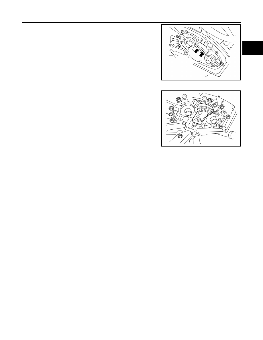
2. Remove the secondary timing chain tensioner shoe by evenly

prying at base of shoe with suitable tool as shown. 

INSTALLATION

1. Install new secondary timing chain tensioner shoe using Tool (A)

as shown.

• Tighten the bolt until the secondary timing chain tensioner

shoe is fully seated on the secondary timing chain tensioner.

CAUTION:

Do not overtighten bolt.

2. Installation of the remaining components is in the reverse order

of removal.

ALBIA0676ZZ

Tool number

:  — (J-50246)

ALBIA0677ZZ

2011 Pathfinder

EM-72

< REMOVAL AND INSTALLATION >

[VQ40DE]

REAR TIMING CHAIN CASE

REAR TIMING CHAIN CASE

Exploded View

INFOID:0000000006708841

Removal and Installation

INFOID:0000000006708842

CAUTION:

• After removing timing chain, do not turn the crankshaft and camshaft separately, or the valves will

strike the pistons.

• Before removing the upper oil pan, remove the crankshaft position sensor (POS).

• Be careful not to damage sensor edges.

REMOVAL

1. Remove oil pan (lower) and (upper). Refer to 

EM-36, "Removal and Installation"

.

2. Remove front timing chain case. Refer to 

EM-53, "Removal and Installation"

.

3. Remove timing chains and related components. Refer to 

EM-61, "Removal and Installation"

 and 

EM-70,

"Removal and Installation (Secondary Timing Chain Tensioner)"

.

4. Remove water pump, if necessary. Refer to 

CO-24, "Removal and Installation"

.

5. Remove rear timing chain case as follows:

AWBIA0860GB

1.

Rear timing chain case

2.

Water drain plug (front)

3.

O-rings

4.

Cylinder block

A.

Refer to installation

2011 Pathfinder

REAR TIMING CHAIN CASE

EM-73

< REMOVAL AND INSTALLATION >

[VQ40DE]

C

D

E

F

G

H

I

J

K

L

M

A

EM

N

P

O

a. Loosen and remove bolts using power tool in reverse order as

shown.

b. Cut liquid gasket using Tool and remove rear timing chain case.

CAUTION:

• Do not remove plate metal cover of oil passage.

• After removal, handle rear timing chain case carefully so

it does not twist, bend, or warp under a load.

6. Remove O-rings from cylinder head and camshaft bracket    (No.

1).

CAUTION:

Do not reuse O-rings.

7. Remove O-rings from cylinder block.

CAUTION:

Do not reuse O-rings.

Tool number

: KV10111100 (J-37228)

PBIC2921E

PBIC2922E

SBIA0496E

PBIC0788E

2011 Pathfinder

EM-74

< REMOVAL AND INSTALLATION >

[VQ40DE]

REAR TIMING CHAIN CASE

8. Use scraper to remove all traces of old liquid gasket from rear

timing chain case, and opposite mating surfaces.

• Remove old liquid gasket from bolt hole and thread.

INSTALLATION

1. Install rear timing chain case as follows:
a. Install new O-rings onto cylinder block.

CAUTION:

Do not reuse O-rings.

b. Install new O-rings to cylinder head and camshaft bracket

(No. 1).

CAUTION:

Do not reuse O-rings.

c.

Apply liquid gasket using Tool to rear timing chain case back side as shown.

CAUTION:

• Use Genuine RTV Silicone Sealant or equivalent. Refer to 

GI-14, "Recommended Chemical Prod-

ucts and Sealants"

.

• Remove water, oil, dust, dirt, or other foreign material on all sealing surfaces prior to installation. 

• The components must be installed within 5 minutes of the liquid gasket application. Then allow

30 minutes for the liquid gasket to set before operating the engine.

PBIC2910E

PBIC2084E

PBIC0788E

SBIA0496E

2011 Pathfinder

REAR TIMING CHAIN CASE

EM-75

< REMOVAL AND INSTALLATION >

[VQ40DE]

C

D

E

F

G

H

I

J

K

L

M

A

EM

N

P

O

• For rear timing chain case water pump opening, completely wipe off liquid gasket covering the

area shown.

• Apply liquid gasket on installation position of water pump and cylinder head completely.

d. Align rear timing chain case with dowel pins (right and left) on cylinder block and install rear timing chain

case.

• Make sure O-rings stay in place during installation to cylinder block, cylinder head and camshaft bracket

(No. 1).

CAUTION:

Do not reuse O-rings.

e. Tighten bolts in numerical order as shown.

• There are two type of bolts with different torque specifications.

Refer to the following for installing bolts. 

f.

After all bolts are tightened, retighten them to the specified torque in numerical order as shown.

• If liquid gasket protrudes, wipe it off immediately.

Bolt length Bolt position

Torque specification

20 mm 
(0.79 in)

1, 2, 3, 6, 7, 8, 
9, 10

: 12.7 N·m (1.3 kg-m, 9 ft-lb)

16 mm 
(0.63 in)

4, 5, 11

: 12.7 N·m (1.3 kg-m, 9 ft-lb)

16 mm 
(0.63 in)

12 through 26 : 15.0 N·m (1.5 kg-m, 11 ft-lb)

PBIC2924E

PBIC2921E

2011 Pathfinder

EM-76

< REMOVAL AND INSTALLATION >

[VQ40DE]

REAR TIMING CHAIN CASE

g. After installing rear timing chain case, check the surface height

difference between following parts on oil pan (upper) mounting

surface.

• If not within the standard, repeat the installation procedure.

2. Install water pump with new O-rings, if removed. Refer to 

CO-24, "Removal and Installation"

.

CAUTION:

Do not reuse O-rings.

3. Install timing chains and related components. Refer to 

EM-61, "Removal and Installation"

 and 

EM-70,

"Removal and Installation (Secondary Timing Chain Tensioner)"

.

4. Install front timing chain case. Refer to 

EM-53, "Removal and Installation"

.

5. Install oil pan (upper) and (lower). Refer to 

EM-36, "Removal and Installation"

.

INSPECTION AFTER INSTALLATION

• Before starting engine, check oil/fluid levels including engine coolant and engine oil. If less than required

quantity, fill to the specified level. Refer to 

MA-18, "FOR USA AND CANADA : Fluids and Lubricants"

 (United

States and Canada) and 

MA-20, "FOR MEXICO : Fluids and Lubricants"

 (Mexico).

• Use procedure below to check for fuel leakage.

• Turn ignition switch ON (with engine stopped). With fuel pressure applied to fuel piping, check for fuel leak-

age at connection points.

• Start engine. With engine speed increased, check again for fuel leakage at connection points.

• Run engine to check for unusual noise and vibration.

NOTE:

If hydraulic pressure inside timing chain tensioner drops after removal and installation, slack in the guide

may generate a pounding noise during and just after engine start. However, this is normal. Noise will stop

after hydraulic pressure rises.

• Warm up engine thoroughly to make sure there is no leakage of fuel, exhaust gas, or any oils/fluids including

engine oil and engine coolant.

• Bleed air from passages in lines and hoses, such as in cooling system.

• After cooling down engine, again check oil/fluid levels including engine oil and engine coolant. Refill to spec-

ified level, if necessary.

• Summary of the inspection items:

*Power steering fluid, brake fluid, etc.

Standard

Rear timing chain case to lower cylinder block:

–0.24 to 0.14 mm (–0.0094 to 0.0055 in)

PBIC2925E

Item

Before starting engine

Engine running

After engine stopped

Engine coolant

Level

Leakage

Level

Engine oil

Level

Leakage

Level

Transmission/
transaxle fluid 

A/T and CVT Models

Leakage

Level/Leakage

Leakage

M/T Models

Level/Leakage

Leakage

Level/Leakage

Other oils and fluids*

Level

Leakage

Level

Fuel

Leakage

Leakage

Leakage

Exhaust gas

Leakage

2011 Pathfinder

CAMSHAFT

EM-77

< REMOVAL AND INSTALLATION >

[VQ40DE]

C

D

E

F

G

H

I

J

K

L

M

A

EM

N

P

O

CAMSHAFT

Exploded View

INFOID:0000000006708846

1.

Intake valve timing control solenoid 
valve (RH bank)

2.

Gasket

3.

Camshaft bracket (No. 2 to 4)

4.

Camshaft (EXH)

5.

Camshaft (INT)

6.

Camshaft bracket (No. 1)

7.

Dowel pin

8.

Valve lifter

9.

O-ring

10.

Timing chain tensioner (secondary) 
(RH bank)

11. Spring

12. Plunger

13.

Timing chain tensioner (secondary) 
(LH bank)

14. Cylinder head (RH bank)

15. Cylinder head (LH bank)

16. O-ring

17.

Camshaft position sensor (PHASE) 
(RH bank)

18.

Camshaft position sensor (PHASE) 
(LH bank)

19. Intake valve timing control solenoid 

valve (LH bank)

PBIC2930E

2011 Pathfinder

EM-78

< REMOVAL AND INSTALLATION >

[VQ40DE]

CAMSHAFT

Removal and Installation

INFOID:0000000006708847

REMOVAL

1. Release the fuel pressure (LH only). Refer to 

EC-484, "Fuel Pressure Check"

.

2. Disconnect the battery negative terminal. Refer to 

PG-76, "Removal and Installation"

.

3. Remove front wheels and tires. Refer to 

WT-50, "Adjustment"

.

4. Remove front fender protectors. Refer to 

EXT-25, "Removal and Installation of Front Fender Protector"

.

5. Remove intake manifold collector. Refer to 

EM-27, "Removal and Installation"

.

6. Remove rocker covers. Refer to 

EM-43, "Removal and Installation"

.

7. Remove front timing chain case, camshaft sprockets, timing chains and rear timing chain case. Refer to

EM-61, "Removal and Installation"

 and 

EM-72, "Removal and Installation"

.

8. Remove camshaft position sensor (PHASE) (right and left

banks) from cylinder head back side.

CAUTION:

• Handle carefully to avoid dropping and shocks.

• Do not disassemble.

• Do not allow metal powder to adhere to magnetic part at

sensor tip.

• Do not place sensors in a location where they are

exposed to magnetism.

9. Remove intake valve timing control solenoid valves.

• Discard intake valve timing control solenoid valve gaskets and

use new gaskets for installation.

10. Remove camshaft brackets.

• Mark camshafts, camshaft brackets and bolts so they are placed in the same position and direction for

installation.

KBIA1046E

WBIA0169E

2011 Pathfinder


Content      ..     368      369      370      371     ..