Nissan Pathfinder (2011 year). Instruction - part 266


  Index      Instructions     Nissan Pathfinder (2011 year) - Service and Repair Instruction


Search            copyright infringement  


Content      ..     264      265      266      267     ..


Nissan Pathfinder (2011 year). Instruction - part 266


EC-182

< DTC/CIRCUIT DIAGNOSIS >

[VQ40DE]

P0139, P0159 HO2S2

1. Start engine and warm it up to normal operating temperature.

2. Select “SELF-LEARNING CONT” in “WORK SUPPORT” mode with CONSULT-III.

3. Clear the self-learning control coefficient by touching “CLEAR”.

4. Run engine for at least 10 minutes at idle speed.

Is the 1st trip DTC P0171, P0172, P0174 or P0175 detected?

Is it difficult to start engine?


Without CONSULT-III

1. Start engine and warm it up to normal operating temperature.

2. Turn ignition switch OFF.

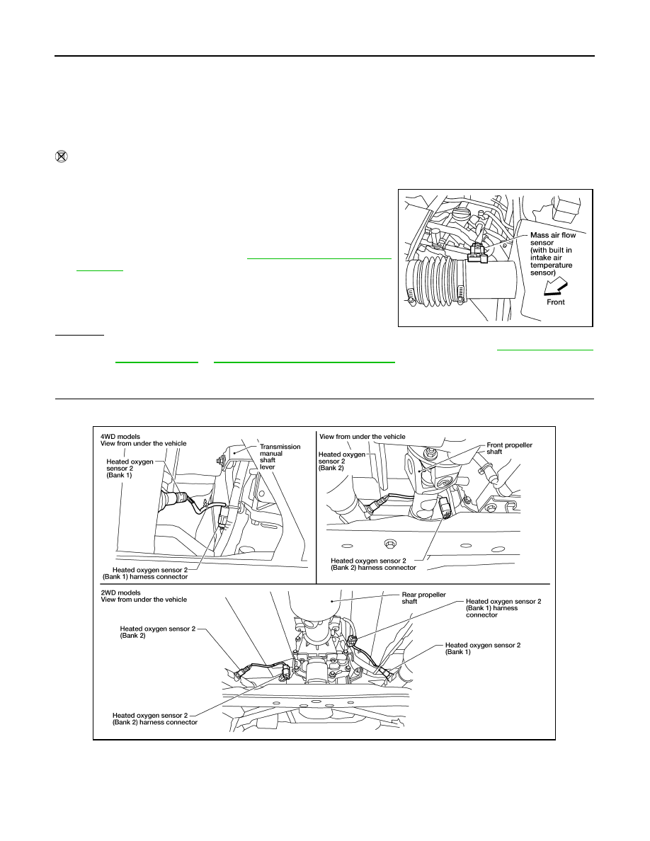
3. Disconnect mass air flow sensor harness connector, and restart

and run engine for at least 5 seconds at idle speed.

4. Stop engine and reconnect mass air flow sensor harness con-

nector.

5. Make sure DTC P0102 is displayed.

6. Erase the DTC memory. Refer to 

EC-74, "On Board Diagnosis

Function"

.

7. Make sure DTC P0000 is displayed.

8. Run engine for at least 10 minutes at idle speed.

Is the 1st trip DTC P0171, P0172, P0174 or P0175 detected?

Is it difficult to start engine?

Yes or No

Yes

>> Perform trouble diagnosis for DTC P0171, P0174 or P0172, P0175. Refer to 

EC-185, "On Board

Diagnosis Logic"

 or 

EC-191, "On Board Diagnosis Logic"

.

No

>> GO TO 3.

3.

CHECK HO2S2 GROUND CIRCUIT FOR OPEN AND SHORT

1. Turn ignition switch OFF.

2. Disconnect heated oxygen sensor 2 harness connector.

3. Disconnect ECM harness connector.

4. Check harness continuity between HO2S2 terminal 4 and ECM terminal 78.

Refer to Wiring Diagram.

BBIA0541E

Continuity should exist.

BBIA0540E

2011 Pathfinder

P0139, P0159 HO2S2

EC-183

< DTC/CIRCUIT DIAGNOSIS >

[VQ40DE]

C

D

E

F

G

H

I

J

K

L

M

A

EC

N

P

O

5. Also check harness for short to ground and short to power.
OK or NG

OK

>> GO TO 4.

NG

>> Repair open circuit or short to ground or short to power in harness or connectors.

4.

CHECK HO2S2 INPUT SIGNAL CIRCUIT FOR OPEN AND SHORT

1. Check harness continuity between ECM terminal and HO2S2 terminal as follows.

Refer to Wiring Diagram.

2. Check harness continuity between the following terminals and ground.

Refer to Wiring Diagram.

3. Also check harness for short to power.
OK or NG

OK

>> GO TO 5.

NG

>> Repair open circuit or short to ground or short to power in harness or connectors.

5.

CHECK HEATED OXYGEN SENSOR 2

Refer to 

EC-183, "Component Inspection"

.

OK or NG

OK

>> GO TO 6.

NG

>> Replace malfunctioning heated oxygen sensor 2. Refer to 

EX-7, "Removal and Installation"

.

6.

CHECK INTERMITTENT INCIDENT

Refer to 

GI-33, "Work Flow"

.

>>

INSPECTION END

Component Inspection

INFOID:0000000006243882

HEATED OXYGEN SENSOR 2

 With CONSULT-III

1. Turn ignition switch ON and select “DATA MONITOR” mode with CONSULT-III.
2. Start engine and warm it up to the normal operating temperature.
3. Turn ignition switch OFF and wait at least 10 seconds.
4. Start engine and keep the engine speed between 3,500 and 4,000 rpm for at least 1 minute under no load.
5. Let engine idle for 1 minute.
6. Select “FUEL INJECTION” in “ACTIVE TEST” mode, and select “HO2S2 (B1)/(B2)” as the monitor item

with CONSULT-III.

DTC

Terminals

Bank

ECM

Sensor

P0139

74

1

1

P0159

55

1

2

Continuity should exist.

DTC

Terminals

Bank

ECM

Sensor

P0139

74

1

1

P0159

55

1

2

Continuity should not exist.

2011 Pathfinder

EC-184

< DTC/CIRCUIT DIAGNOSIS >

[VQ40DE]

P0139, P0159 HO2S2

7. Check “HO2S2 (B1)/(B2)” at idle speed when adjusting “FUEL INJECTION” to 

±

25%.

“HO2S2 (B1)/(B2)” should be above 0.68V at least once when the “FUEL INJECTION” is +25%.

“HO2S2 (B1)/(B2)” should be below 0.18V at least once when the “FUEL INJECTION” is 

25%.

CAUTION:

• Discard any heated oxygen sensor which has been dropped from a height of more than 0.5 m (19.7

in) onto a hard surface such as a concrete floor; use a new one.

• Before installing new oxygen sensor, clean exhaust system threads using Oxygen Sensor Thread

Cleaner tool J-43897-18 or J-43897-12 and approved anti-seize lubricant.

 Without CONSULT-III

1. Start engine and warm it up to the normal operating temperature.
2. Turn ignition switch OFF and wait at least 10 seconds.
3. Start engine and keep the engine speed between 3,500 and 4,000 rpm for at least 1 minute under no load.
4. Let engine idle for 1 minute.
5. Set voltmeter probes between ECM terminal 74 [HO2S2 (B1) signal] or 55 [HO2S2 (B2) signal] and

ground.

6. Check the voltage when revving up to 4,000 rpm under no load

at least 10 times.

(Depress and release accelerator pedal as soon as possible.)

The voltage should be above 0.68V and below 0.18V at least

once during this procedure.

If the voltage can be confirmed at step 6, step 7 is not nec-

essary.

7. Keep vehicle at idling for 10 minutes, then check voltage. Or

check the voltage when coasting from 80 km/h (50 MPH) in D

position with “OD” OFF.

The voltage should be above 0.68V and below 0.18V at least

once during this procedure.

8. If NG, replace heated oxygen sensor 2. Refer to 

EX-7, "Removal and Installation"

.

CAUTION:

• Discard any heated oxygen sensor which has been dropped from a height of more than 0.5 m (19.7

in) onto a hard surface such as a concrete floor; use a new one.

• Before installing new oxygen sensor, clean exhaust system threads using Oxygen Sensor Thread

Cleaner tool J-43897-18 or J-43897-12 and approved anti-seize lubricant.

PBIB3458E

PBIB1607E

2011 Pathfinder

P0171, P0174 FUEL INJECTION SYSTEM FUNCTION

EC-185

< DTC/CIRCUIT DIAGNOSIS >

[VQ40DE]

C

D

E

F

G

H

I

J

K

L

M

A

EC

N

P

O

P0171, P0174 FUEL INJECTION SYSTEM FUNCTION

On Board Diagnosis Logic

INFOID:0000000006243883

With the Air-Fuel Mixture Ratio Self-Learning Control, the actual mixture ratio can be brought closely to the

theoretical mixture ratio based on the mixture ratio feedback signal from the air fuel ratio (A/F) sensor 1. The

ECM calculates the necessary compensation to correct the offset between the actual and the theoretical

ratios.

In case the amount of the compensation value is extremely large (the actual mixture ratio is too lean), the

ECM judges the condition as the fuel injection system malfunction and illuminates the MIL (2 trip detection

logic).

DTC Confirmation Procedure

INFOID:0000000006243884

NOTE:

If DTC Confirmation Procedure has been previously conducted, always turn ignition switch OFF and wait at

least 10 seconds before conducting the next test.

 WITH CONSULT-III

1. Start engine and warm it up to normal operating temperature.
2. Turn ignition switch OFF and wait at least 10 seconds.
3. Turn ignition switch ON and select “SELF-LEARNING CONT” in “WORK SUPPORT” mode with CON-

SULT-III.

4. Clear the self-learning control coefficient by touching “CLEAR”.
5. Start engine.

If it is difficult to start engine, the fuel injection system has a malfunction.

Performing the following procedure is advised.

a. Crank engine while depressing accelerator pedal.

NOTE:

When depressing accelerator pedal three-fourths (3/4) or more, the control system does not start the

engine. Do not depress accelerator pedal too much.

b. If engine starts, go to 

EC-186, "Diagnosis Procedure"

.

If engine does not start, check exhaust and intake air leakage visually.

6. Keep engine at idle for at least 5 minutes.
7. Check 1st trip DTC.
8. The 1st trip DTC P0171 or P0174 should be detected at this stage, if a malfunction exists. If so, go to 

EC-

186, "Diagnosis Procedure"

.

NOTE:

If 1st trip DTC is not detected during above procedure, performing the following procedure is advised.

a. Turn ignition switch OFF and wait at least 10 seconds.
b. Start engine.
c. Maintain the following conditions for at least 10 consecutive minutes.

Sensor

Input signal to ECM

ECM function

Actuator

A/F sensor 1

Density of oxygen in exhaust gas
(Mixture ratio feedback signal)

Fuel injection 
control

Fuel injector

DTC No.

Trouble diagnosis 

name

DTC detecting condition

Possible cause

P0171
0171
(Bank 1)

Fuel injection system 
too lean

• Fuel injection system does not operate properly.
• The amount of mixture ratio compensation is too 

large. (The mixture ratio is too lean.)

• Intake air leaks
• Air fuel ratio (A/F) sensor 1
• Fuel injector
• Exhaust gas leaks
• Incorrect fuel pressure
• Lack of fuel
• Mass air flow sensor
• Incorrect PCV hose connection

P0174
0174
(Bank 2)

2011 Pathfinder

EC-186

< DTC/CIRCUIT DIAGNOSIS >

[VQ40DE]

P0171, P0174 FUEL INJECTION SYSTEM FUNCTION

Hold the accelerator pedal as steady as possible.

CAUTION:

Always drive vehicle at a safe speed.

d. Check 1st trip DTC.
e. If 1st trip DTC is detected, go to 

EC-186, "Diagnosis Procedure"

.

 WITH GST

1. Start engine and warm it up to normal operating temperature.
2. Turn ignition switch OFF and wait at least 10 seconds.
3. Disconnect mass air flow sensor harness connector.
4. Restart engine and let it idle for at least 5 seconds.
5. Stop engine and reconnect mass air flow sensor harness con-

nector.

6. Select Service $03 with GST. Check that DTC P0102 is

detected.

7. Select Service $04 with GST and erase the DTC P0102.
8. Start engine.

If it is difficult to start engine, the fuel injection system has a mal-

function.

Performing the following procedure is advised.

a. Crank engine while depressing accelerator pedal.

NOTE:

When depressing accelerator pedal three-fourths (3/4) or more, the control system does not start the

engine. Do not depress accelerator pedal too much.

b. If engine starts, go to 

EC-186, "Diagnosis Procedure"

If engine does not start, check exhaust and intake air leakage visually.

9. Keep engine at idle for at least 5 minutes.
10. Check 1st trip DTC.
11. The 1st trip DTC P0171 or P0174 should be detected at this stage, if a malfunction exists. If so, go to 

EC-

186, "Diagnosis Procedure"

.

NOTE:

If 1st trip DTC is not detected during above procedure, performing the following procedure is advised.

a. Turn ignition switch OFF and wait at least 10 seconds.
b. Start engine.
c.

Maintain the following conditions for at least 10 consecutive minutes.

Hold the accelerator pedal as steady as possible.

CAUTION:

Always drive vehicle at a safe speed.

d. Check 1st trip DTC.
e. If 1st trip DTC is detected, go to 

EC-186, "Diagnosis Procedure"

.

Diagnosis Procedure

INFOID:0000000006243885

1.

CHECK EXHAUST GAS LEAK

1. Start engine and run it at idle.

VHCL SPEED SE

50 - 120 km/h (31 - 75 MPH)

VHCL SPEED SE

50 - 120 km/h (31 - 75 MPH)

BBIA0541E

2011 Pathfinder

P0171, P0174 FUEL INJECTION SYSTEM FUNCTION

EC-187

< DTC/CIRCUIT DIAGNOSIS >

[VQ40DE]

C

D

E

F

G

H

I

J

K

L

M

A

EC

N

P

O

2. Listen for an exhaust gas leak before three way catalyst (manifold).

OK or NG

OK

>> GO TO 2.

NG

>> Repair or replace.

2.

CHECK FOR INTAKE AIR LEAK

1. Listen for an intake air leak after the mass air flow sensor.

2. Check PCV hose connection.
OK or NG

OK

>> GO TO 3.

NG

>> Repair or replace.

3.

CHECK A/F SENSOR 1 INPUT SIGNAL CIRCUIT

1. Turn ignition switch OFF.

2. Disconnect corresponding A/F sensor 1 harness connector.

3. Disconnect ECM harness connector.

4. Check harness continuity between A/F sensor 1 terminal and ECM terminal as follows.

Refer to Wiring Diagram.

5. Check harness continuity between the following terminals and ground.

Refer to Wiring Diagram.

PBIB1216E

A/F sensor 1 terminal

ECM terminal

Bank 1

1

35

2

56

Bank 2

1

16

2

75

Continuity should exist.

Bank 1

Bank 2

A/F sensor 1 terminal

ECM terminal

A/F sensor 1 terminal

ECM terminal

1

35

1

16

2

56

2

75

Continuity should not exist.

BBIA0544E

2011 Pathfinder

EC-188

< DTC/CIRCUIT DIAGNOSIS >

[VQ40DE]

P0171, P0174 FUEL INJECTION SYSTEM FUNCTION

6. Also check harness for short to power.
OK or NG

OK

>> GO TO 4.

NG

>> Repair open circuit or short to ground or short to power in harness or connectors.

4.

CHECK FUEL PRESSURE

1. Release fuel pressure to zero. Refer to 

EC-484, "Fuel Pressure Check"

.

2. Install fuel pressure gauge and check fuel pressure. Refer to 

EC-484, "Fuel Pressure Check"

.

OK or NG

OK (With CONSULT-III)>>GO TO 6.

OK (Without CONSULT-III)>>GO TO 7.

NG

>> GO TO 5.

5.

DETECT MALFUNCTIONING PART

Check the following.

• Fuel pump and circuit (Refer to 

EC-403, "Diagnosis Procedure"

.)

• Fuel pressure regulator (Refer to 

EC-484, "Fuel Pressure Check"

.)

• Fuel lines

• Fuel filter for clogging

>> Repair or replace.

6.

CHECK MASS AIR FLOW SENSOR

With CONSULT-III

1. Install all removed parts.

2. Check “MASS AIR FLOW” in “DATA MONITOR” mode with CONSULT-III.

OK or NG

OK

>> GO TO 8.

NG

>> Check connectors for rusted terminals or loose connections in the mass air flow sensor circuit or

ground. Refer to 

EC-118, "Component Description"

.

7.

CHECK MASS AIR FLOW SENSOR

With GST

1. Install all removed parts.

2. Check mass air flow sensor signal in Service $01 with GST.

OK or NG

OK (P0171)>>GO TO 9.

OK (P0174)>>GO TO 11.

NG

>> Check connectors for rusted terminals or loose connections in the mass air flow sensor circuit or

ground. Refer to 

EC-118, "Component Description"

.

8.

CHECK FUNCTION OF FUEL INJECTOR

With CONSULT-III

1. Start engine.

2. Perform “POWER BALANCE” in “ACTIVE TEST” mode with CONSULT-III.

3. Make sure that each circuit produces a momentary engine speed drop.

At idling: 350 kPa (3.57 kg/cm

2

, 51 psi)

2.0 - 6.0 g/s:

at idling

7.0 - 20.0 g/s:

at 2,500 rpm

2.0 - 6.0 g/s:

at idling

7.0 - 20.0 g/s:

at 2,500 rpm

2011 Pathfinder

P0171, P0174 FUEL INJECTION SYSTEM FUNCTION

EC-189

< DTC/CIRCUIT DIAGNOSIS >

[VQ40DE]

C

D

E

F

G

H

I

J

K

L

M

A

EC

N

P

O

OK or NG

OK

>> GO TO 12.

NG

>> Perform trouble diagnosis for FUEL INJECTOR, refer to 

EC-399, "Component Description"

.

9.

CHECK FUNCTION OF FUEL INJECTOR-I

Without CONSULT-III

1. Stop engine.

2. Disconnect harness connector F44 (3), F201 (1)

3. Turn ignition switch ON.

4. Check voltage between harness connector F44 terminal 3 and

ground with CONSULT-III or tester.

5. Turn ignition switch OFF.

6. Disconnect ECM harness connector.

7. Check harness continuity between harness connector F44 and

ECM as follows.

Refer to Wiring Diagram.

8. Also check harness for short to ground and short to power.
OK or NG

OK

>> GO TO 10.

NG

>> Perform trouble diagnosis for FUEL INJECTOR, refer to 

EC-399, "Component Description"

.

10.

CHECK FUNCTION OF FUEL INJECTOR-II

Provide battery voltage between harness connector F201 as follows

and then interrupt it. Listen to each fuel injector operating sound.

OK or NG

2

: Vacuum tank

: Front

AWBIA0686ZZ

Voltage: Battery voltage

Cylinder

Harness connector F44 

terminal

ECM terminal

1

2

23

3

1

22

5

4

21

Continuity should exist.

PBIB2633E

Cylinder

Harness connector F201 terminal

(+)

(–)

1

3

2

3

3

1

5

3

4

Operating sound should exist.

PBIB2634E

2011 Pathfinder


Content      ..     264      265      266      267     ..