Nissan Pathfinder (2011 year). Instruction - part 227


  Index      Instructions     Nissan Pathfinder (2011 year) - Service and Repair Instruction


Search            copyright infringement  


Content      ..     225      226      227      228     ..


Nissan Pathfinder (2011 year). Instruction - part 227


DLN-354

< REMOVAL AND INSTALLATION >

[FRONT FINAL DRIVE: R180A]

SIDE OIL SEAL

SIDE OIL SEAL

Removal and Installation

INFOID:0000000006245180

REMOVAL

1. Remove the drive shafts from the front final drive assembly. Refer to 

FAX-7, "VQ40DE : Removal and

Installation"

.

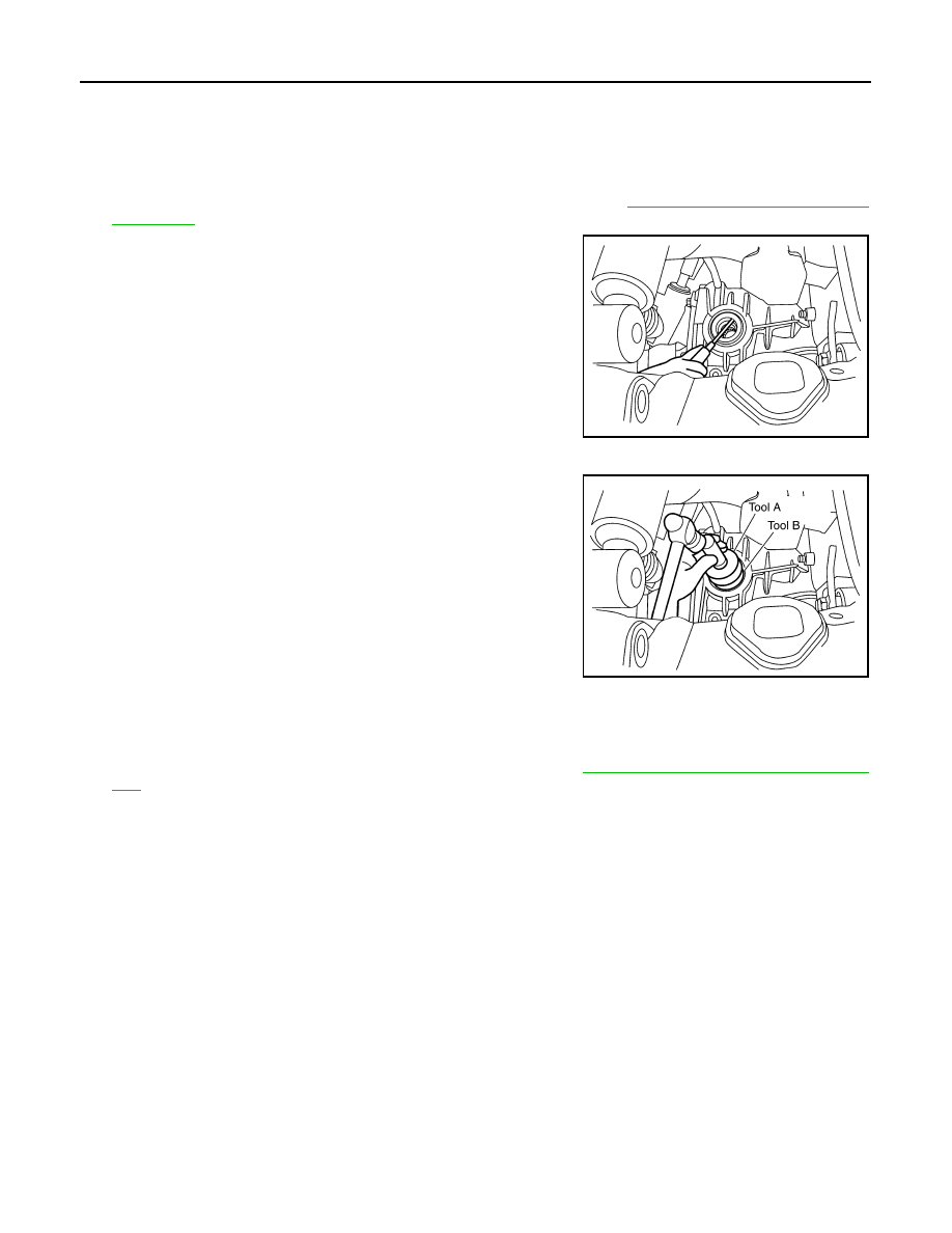
2. Remove the side oil seal using suitable tool.

CAUTION:

Do not reuse the side oil seal.

INSTALLATION

1. Apply multi-purpose grease to the lips and differential gear oil to

the circumference of the new side oil seal. Then drive the new

side oil seal in evenly until it becomes flush with the gear carrier

using Tools.

CAUTION:

• Do not reuse side oil seal.

• Do not incline the new side oil seal when installing.

• Apply multi-purpose grease to the lips and differential

gear oil to the circumference of the new side oil seal.

2. Installation of the remaining components is in the reverse order of removal.

CAUTION:

Check the differential gear oil level after installation. Refer to 

DLN-351, "Checking Differential Gear

Oil"

.

LDIA0173E

Tool number

A: ST30720000 (J-25405)
B: ST27863000 ( — )

PDIA0826E

2011 Pathfinder

CARRIER COVER

DLN-355

< REMOVAL AND INSTALLATION >

[FRONT FINAL DRIVE: R180A]

C

E

F

G

H

I

J

K

L

M

A

B

DLN

N

O

P

CARRIER COVER

Removal and Installation

INFOID:0000000006245181

REMOVAL

1. Drain the differntial gear oil. Refer to 

DLN-351, "Changing Differential Gear Oil"

.

2. Remove the front final drive assembly. Refer to 

DLN-356, "Removal and Installation"

.

3. Remove the carrier cover bolts and separate the carrier cover

from the gear carrier using Tool.

CAUTION:

• Do not damage the mating surface.

• Do not insert flat-bladed screwdriver, this will damage the

mating surface.

INSTALLATION

1. Apply a 3 mm (0.12 in) bead of sealant to the mating surface of

the carrier cover as shown.

• Use Genuine Silicone RTV or equivalent. Refer to 

GI-14,

"Recommended Chemical Products and Sealants"

.

CAUTION:

Remove any old sealant adhering to the mating surfaces.

Also remove any moisture, oil, or foreign material adhering

to the application and mating surfaces.

2. Install the carrier cover to the gear carrier. Tighten the bolts to

the specified torque. Refer to 

DLN-359, "Disassembly and

Assembly"

.

3. Install the front final drive assembly. Refer to 

DLN-356,

"Removal and Installation"

.

CAUTION:

Fill the front final drive assembly with recommended differential gear oil. Refer to 

DLN-351

.

Tool number

: KV10111100 (J-37228)

PDIA0699E

PDIA0712E

2011 Pathfinder

DLN-356

< UNIT REMOVAL AND INSTALLATION >

[FRONT FINAL DRIVE: R180A]

FRONT FINAL DRIVE ASSEMBLY

UNIT REMOVAL AND INSTALLATION

FRONT FINAL DRIVE ASSEMBLY

Removal and Installation

INFOID:0000000006245182

REMOVAL

NOTE:

When removing components such as hoses, tubes/lines, etc., cap or plug openings to prevent fluid from spill-

ing.
1. Remove the drive shafts from the front final drive assembly. Refer to 

FAX-7, "VQ40DE : Removal and

Installation"

.

2. Remove the front crossmember.

1.

Breather hose

2.

Front final drive assembly

3.

Front crossmember

Front

AWDIA0018GB

2011 Pathfinder

FRONT FINAL DRIVE ASSEMBLY

DLN-357

< UNIT REMOVAL AND INSTALLATION >

[FRONT FINAL DRIVE: R180A]

C

E

F

G

H

I

J

K

L

M

A

B

DLN

N

O

P

3. Remove the front propeller shaft from the front final drive assembly. Refer to 

DLN-318, "Removal and

Installation"

.

4. Disconnect the vent hose from the front final drive assembly.
5. Support the front final drive assembly using a suitable jack.
6. Remove the front final drive assembly bolts, then remove the

front final drive assembly.

WARNING:

Support the front final drive assembly while removing using

a suitable jack.

INSTALLATION

Installation is in the reverse order of removal.

• Install new side oil seals into the front final drive assembly. Refer to 

DLN-354, "Removal and Installation"

.

CAUTION:

• Make sure there are no pinched or restricted areas on the breather hose caused by folding or bend-

ing when installing it.

• Fill the front final drive assembly with differential gear oil after installation. Refer to 

DLN-351

.

WDIA0145E

2011 Pathfinder

DLN-358

< UNIT DISASSEMBLY AND ASSEMBLY >

[FRONT FINAL DRIVE: R180A]

FRONT FINAL DRIVE

UNIT DISASSEMBLY AND ASSEMBLY

FRONT FINAL DRIVE

Exploded View

INFOID:0000000006245183

1.

Drive pinion lock nut

2.

Companion flange

3.

Front oil seal

4.

Drive pinion front bearing

5.

Gear carrier

6.

Side oil seal

7.

Bushing

8.

Differential side shaft

9.

Differential side shaft bearing

10. Snap ring

11. Snap ring

12. Gasket

13. Drain plug

14. Collapsible spacer

15. Drive pinion rear bearing

16. Drive pinion height adjusting washer 17. Drive pinion

18. Side bearing adjusting washer

19. Side bearing

20. Side gear thrust washer

21. Side gear

22. Pinion mate shaft

23. Lock pin

24. Pinion mate gear

25. Pinion mate thrust washer

26. Drive gear

27. Differential case

28. Housing spacer

29. Side bearing cap

30. Filler plug

AWDIA0750GB

2011 Pathfinder

FRONT FINAL DRIVE

DLN-359

< UNIT DISASSEMBLY AND ASSEMBLY >

[FRONT FINAL DRIVE: R180A]

C

E

F

G

H

I

J

K

L

M

A

B

DLN

N

O

P

Disassembly and Assembly

INFOID:0000000006245184

ASSEMBLY INSPECTION AND ADJUSTMENT

• Drain the differential gear oil before inspection and adjustment. Refer to 

DLN-351

.

• Remove and install the carrier cover as necessary for inspection and adjustment. Refer to 

DLN-355

.

Total Preload Torque

1. Install the differential side shaft if necessary. Refer to 

DLN-354, "Removal and Installation"

.

CAUTION:

The differential side shaft must be installed in order to measure total preload torque. 

2. Rotate the drive pinion back and forth 2 to 3 times to check for unusual noise and rotation malfunction.
3. Rotate the drive pinion at least 20 times to check for smooth operation of the bearings.
4. Measure total preload torque using Tool.

NOTE:

Total preload torque = Drive pinion bearing preload torque +

Side bearing preload torque

• If the measured value is out of the specification, check and adjust each part. Adjust the drive pinion

bearing preload torque first, then adjust the side bearing preload torque.

CAUTION:

Select a side bearing adjusting washer for right and left individually.

Drive Gear Runout

1. Fit a dial indicator to the drive gear back face.
2. Rotate the drive gear to measure runout.

• If the runout is outside of the limit, check the condition of the drive

gear assembly. Foreign material may be caught between the drive

gear and differential case, or the differential case or drive gear may

be deformed.

CAUTION:

31. Carrier cover

A.

Seal lip

B.

Screw hole

C.

Refer to INSTALLATION

Tool number

: ST3127S000 (J-25765-A)

Total preload torque:

Refer to 

DLN-377, "Inspection 

and Adjustment"

PDIA0697E

If the total preload torque is greater than specification

On drive pinion bearings: Replace the collapsible spacer.
On side bearings:

Use thinner side bearing adjusting washers by the same 
amount on each side. Refer to 

DLN-377, "Inspection and Adjust-

ment"

.

If the total preload torque is less than specification

On drive pinion bearings: Tighten the drive pinion lock nut.
On side bearings:

Use thicker side bearing adjusting washers by the same 
amount on each side. Refer to 

DLN-377, "Inspection and Adjust-

ment"

.

Runout limit:

Refer to 

DLN-377, "Inspection and 

Adjustment"

SPD886

2011 Pathfinder

DLN-360

< UNIT DISASSEMBLY AND ASSEMBLY >

[FRONT FINAL DRIVE: R180A]

FRONT FINAL DRIVE

Replace drive gear and drive pinion as a set.

Tooth Contact

1. Apply red lead to the drive gear.

NOTE:

Apply red lead to both faces of three to four gears, at four loca-

tions evenly spaced on the drive gear.

2. Rotate the drive gear back and forth several times. Then check

for correct drive pinion to drive gear tooth contact as shown.

CAUTION:

Check tooth contact on drive side and reverse side.

• If the tooth contact is improperly adjusted, adjust the drive pin-

ion height (dimension X).

- If the tooth contact is near the face (face contact), or near the

heel (heel contact), use a thicker drive pinion height adjusting

washer to move drive pinion closer to the drive gear.

Refer to 

DLN-377, "Inspection and Adjustment"

.

SPD357

SDIA0570E

SDIA0517E

PDIA0440E

2011 Pathfinder

FRONT FINAL DRIVE

DLN-361

< UNIT DISASSEMBLY AND ASSEMBLY >

[FRONT FINAL DRIVE: R180A]

C

E

F

G

H

I

J

K

L

M

A

B

DLN

N

O

P

- If the tooth contact is near the flank (flank contact), or near the

toe (toe contact), use a thinner drive pinion height adjusting

washer to move the drive pinion farther from the drive gear.

Refer to 

DLN-377, "Inspection and Adjustment"

.

Backlash

1. Fit a dial indicator to the drive gear face to measure the back-

lash.

• If the backlash is outside of the specification, change the thick-

ness of the side bearing adjusting washers.

CAUTION:

Do not change the total thickness of side bearing adjusting washers as it will change the side

bearing preload torque.

Companion Flange Runout

1. Rotate companion flange and check for runout on the compan-

ion flange face (inner side of the bolt holes) and companion

flange inner side (socket diameter) using suitable tool.

2. If the runout is outside the runout limit, follow the procedure

below to adjust.

a. Rotate the companion flange on the drive pinion by 90

°

, 180

°

and 270

°

 while checking for the position where the runout is

minimum.

b. If the runout is still outside of the runout limit after the companion flange has been rotated on the drive pin-

ion, possible cause could be an assembly malfunction of drive pinion and drive pinion bearing or a mal-

functioning drive pinion bearing.

c. If the runout is still outside of the runout limit after repair of the assembly of drive pinion and drive pinion

bearing or drive pinion bearing, replace the companion flange.

DISASSEMBLY

Differential side shaft

1. Drain the differential gear oil if necessary.

PDIA0441E

Backlash:

Refer to 

DLN-377, "Inspection and 

Adjustment"

If the backlash is greater than specification:

Make side bearing adjusting washer thicker on drive 
gear back side, and side bearing adjusting washer 
thinner on drive gear tooth side by the same amount. 
Refer to 

DLN-377, "Inspection and Adjustment"

.

If the backlash is less than specification:

Make side bearing adjusting washer thinner on drive 
gear back side, and side bearing adjusting washer 
thicker on drive gear tooth side by the same amount. 
Refer to 

DLN-377, "Inspection and Adjustment"

.

SPD513

Runout limit:

Refer to 

DLN-377, "Inspection and 

Adjustment"

SDIA2078E

2011 Pathfinder


Content      ..     225      226      227      228     ..