Nissan Pathfinder (2011 year). Instruction - part 188
DLN-42
< DTC/CIRCUIT DIAGNOSIS >
[TRANSFER: ATX14B]
P1814 WAIT DETECTION SWITCH
P1814 WAIT DETECTION SWITCH
Description
INFOID:0000000006244949
The wait detection switch detects if the transfer case is in 4WD. DTC P1814 will set if an improper signal from
the wait detection switch is input due to open or short circuit.
DTC Logic
INFOID:0000000006244950
DTC DETECTION LOGIC
DTC CONFIRMATION PROCEDURE
1.
DTC CONFIRMATION PROCEDURE
1. Turn ignition switch ON.
2. Perform self-diagnosis.
Is DTC P1814 detected?
YES
>> Perform diagnosis procedure. Refer to
.
NO
>> Inspection End.
Diagnosis Procedure
INFOID:0000000006244951
Regarding Wiring Diagram information, refer to
1.
CHECK WAIT DETECTION SWITCH SIGNAL
With CONSULT-III
1. Start engine.
2. Select “DATA MONITOR” mode for “ALL MODE AWD/4WD” with CONSULT-III.
3. Read out the value of “WAIT DETCT SW”.
Without CONSULT-III
1. Start engine.
DTC
CONSULT-III
Diagnostic item is detected when...
Reference
[P1814]
4WD DETECT SWITCH
Improper signal from wait detection
switch is input due to open or short cir-
cuit.
Refer to
.
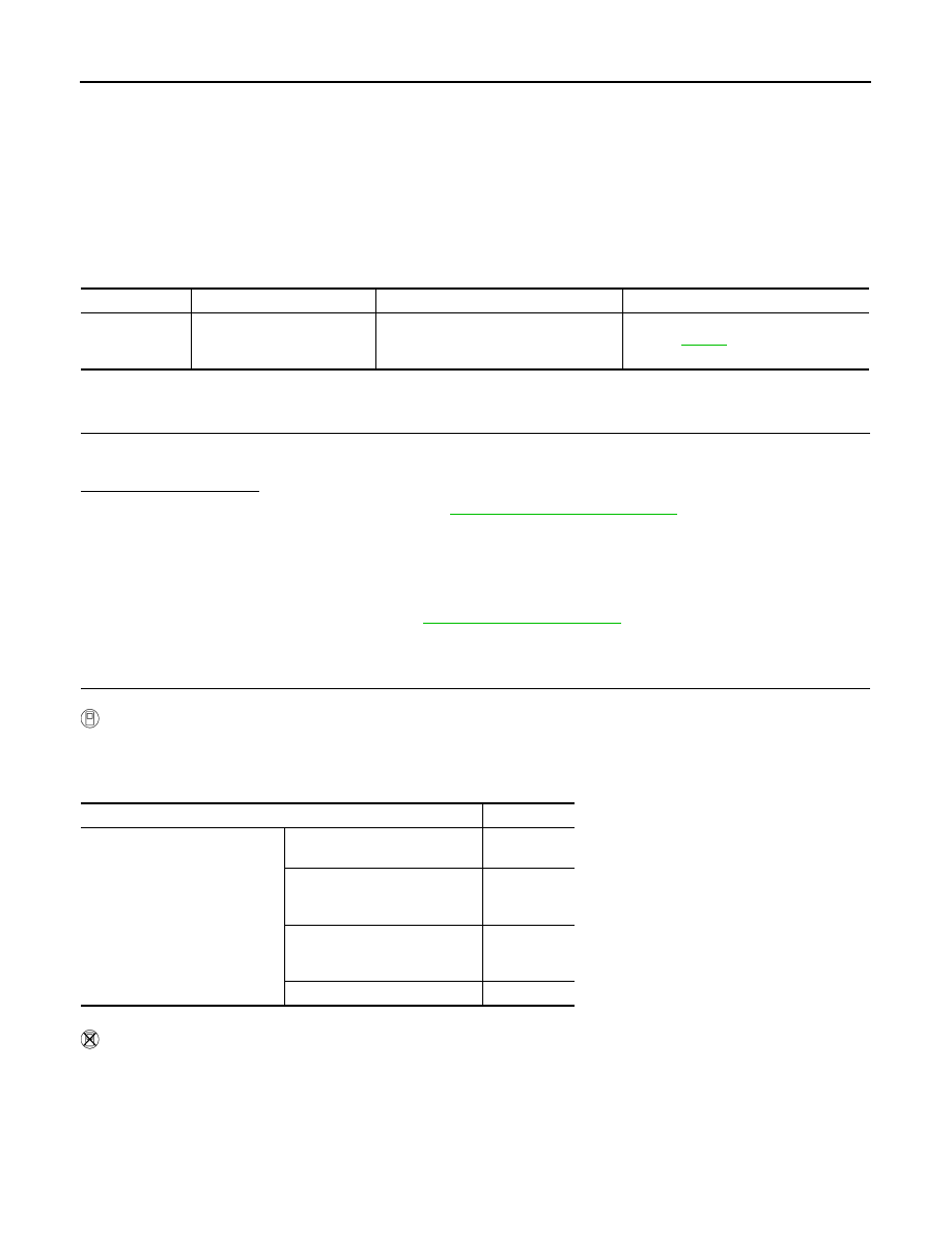
Condition
Display value
• Vehicle stopped
• Engine running
• A/T selector lever “N” position
• Brake pedal depressed
4WD shift switch: 2WD, AUTO
or 4H
OFF
4WD shift switch: 4H to 4LO
(While actuator motor is operat-
ing.)
OFF
→
ON
4WD shift switch: 4LO to 4H
(While actuator motor is operat-
ing.)
ON
→
OFF
4WD shift switch: 4LO
ON
2011 Pathfinder