Nissan Pathfinder (2008 year). Instruction - part 47
 

  Index      Instructions     Nissan Pathfinder (2008 year) - Service and Repair Instruction


Search            copyright infringement  


Content      ..     45      46      47      48     ..


Nissan Pathfinder (2008 year). Instruction - part 47


AV-216

< COMPONENT DIAGNOSIS >

[BOSE AUDIO WITHOUT NAVIGATION]

SOUND SIGNAL CIRCUIT

SOUND SIGNAL CIRCUIT

SATELLITE RADIO TUNER

SATELLITE RADIO TUNER : Description

INFOID:0000000001450748

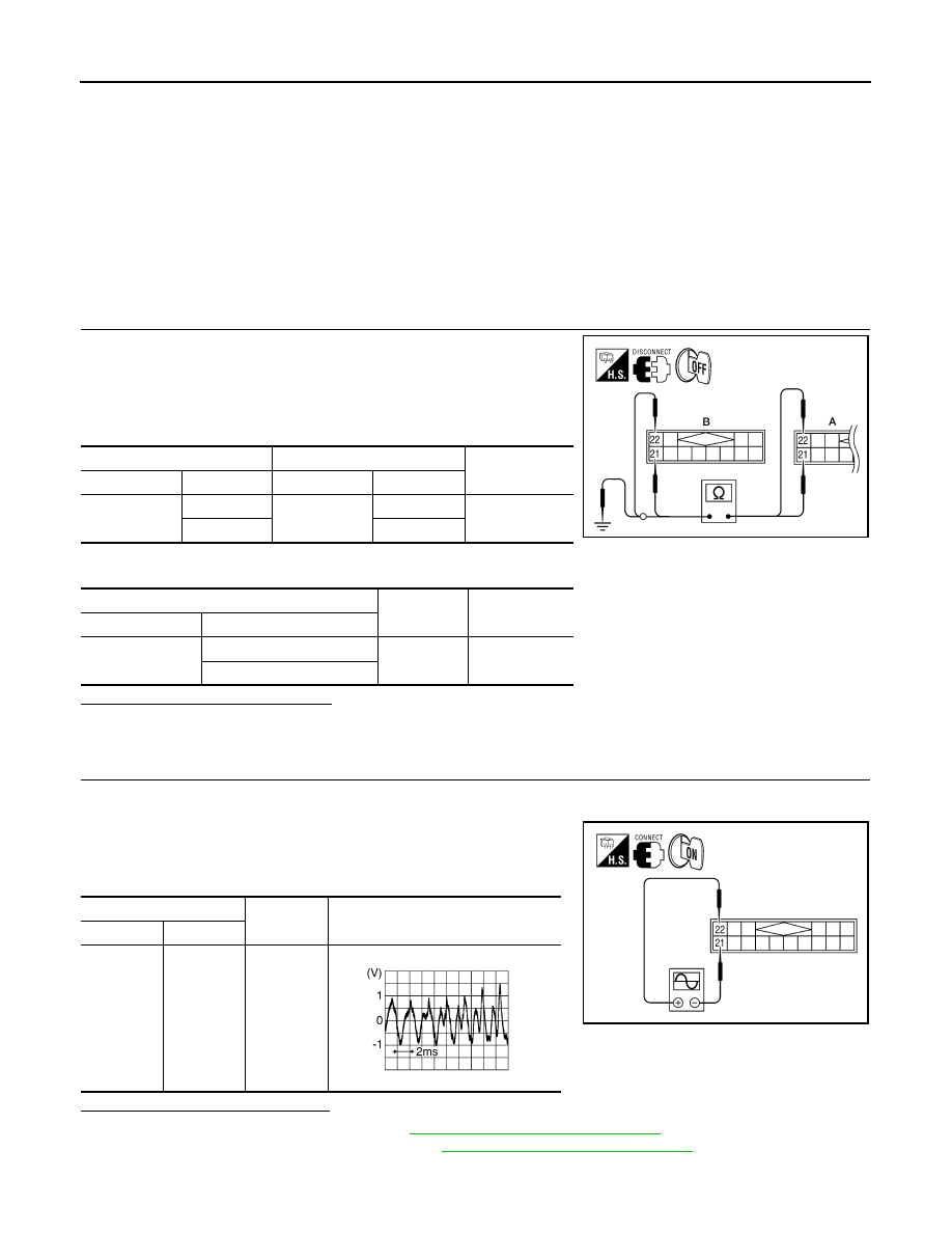
Left and right channel audio signals are supplied from the satellite radio tuner to the AV control unit through
the sound signal circuits.

SATELLITE RADIO TUNER : Diagnosis Procedure

INFOID:0000000001450749

LEFT CHANNEL

1.

CHECK HARNESS

1.

Turn ignition switch OFF.

2.

Disconnect satellite radio tuner (factory installed) connector M41
and AV control unit connector M43.

3.

Check continuity between satellite radio tuner (factory installed)
connector M41 (A)  and AV control unit connector M43 (B).

4.

Check continuity between satellite radio tuner (factory installed) connector M41 (A) and ground.

Are continuity results as specified?

YES

>> GO TO 2

NO

>> Repair harness or connector.

2.

CHECK LEFT CHANNEL AUDIO SIGNAL

1.

Connect satellite radio tuner (factory installed) and AV control unit.

2.

Turn ignition switch ON.

3.

Check signal between satellite radio tuner (factory installed)
connector M41 terminals 21 and 22 with CONSULT-III or oscillo-
scope.

Are voltage readings as specified?

YES

>> Replace AV control unit. Refer to 

AV-266, "Removal and Installation"

.

NO

>> Replace satellite radio tuner. Refer to 

AV-276, "Removal and Installation"

.

RIGHT CHANNEL

A

B

Continuity

Connector

Terminal

Connector

Terminal

M41

21

M43

21

Yes

22

22

A

—

Continuity

Connector

Terminal

M41

21

Ground

No

22

ALNIA0337GB

(+)

(-)

Reference signal

Connector

Terminal

M41

22

21

ALNIA0880GB

SKIB3609E

AV

SOUND SIGNAL CIRCUIT

AV-217

< COMPONENT DIAGNOSIS >

[BOSE AUDIO WITHOUT NAVIGATION]

C

D

E

F

G

H

I

J

K

L

M

B

A

O

P

1.

CHECK HARNESS

1.

Turn ignition switch OFF.

2.

Disconnect satellite radio tuner (factory installed) connector M41
and AV control unit connector M43.

3.

Check continuity between satellite radio tuner (factory installed)
M41 (A) and AV control unit M43 (B).

4.

Check continuity between satellite radio tuner (factory installed) connector M41 (A) and ground.

Are continuity results as specified?

YES

>> GO TO 2

NO

>> Repair harness or connector.

2.

CHECK RIGHT CHANNEL AUDIO SIGNAL

1.

Connect satellite radio tuner (factory installed) and AV control unit.

2.

Turn ignition switch ON.

3.

Check signal between satellite radio tuner (factory installed)
connector M41 terminals 23 and 24 with CONSULT-III or oscillo-
scope.

Are voltage readings as specified?

YES

>> Replace AV control unit. Refer to 

AV-266, "Removal and Installation"

.

NO

>> Replace satellite radio tuner. Refer to 

AV-276, "Removal and Installation"

.

A

B

Continuity

Connector

Terminal

Connector

Terminal

M41

23

M43

23

Yes

24

24

A

—

Continuity

Connector

Terminal

M41

23

Ground

No

24

ALNIA0338GB

(+)

(-)

Reference signal

Connector

Terminal

M41

24

23

ALNIA0881GB

SKIB3609E

AV-218

< ECU DIAGNOSIS >

[BOSE AUDIO WITHOUT NAVIGATION]

AV CONTROL UNIT

ECU DIAGNOSIS

AV CONTROL UNIT

Reference Value

INFOID:0000000001468872

VALUES ON THE DIAGNOSIS TOOL

CONSULT-III data monitor item

TERMINAL LAYOUT

PHYSICAL VALUES

Display Item

Dis-
play

Vehicle status

Remarks

VHCL SPD SIG

ON

Vehicle speed >0 km/h (0 MPH)

Changes in indication may be delayed. This is nor-
mal.

OFF

Vehicle speed =0 km/h (0 MPH)

PKB SIG

ON

Parking brake is applied.

Changes in indication may be delayed. This is nor-
mal.

OFF

Parking brake is released.

ILLUM SIG

ON

Block the light beam from the auto 
light optical sensor when the light SW 
is ON .

—

OFF

Expose the auto light optical sensor 
to light when the light SW is OFF or 
ON.

IGN SIG

ON

Ignition switch ON

—

OFF

Ignition switch in ACC position

REV SIG

ON

Selector lever in R position

Changes in indication may be delayed. This is nor-
mal.

OFF

Selector lever in any position other 
than R

AWNIA0146ZZ

Terminal

(Wire color)

Description

Condition

Reference value

(Approx.)

+

–

Signal name

Input/

Output

6

(Y)

15

Steering switch signal A

Input

Ignition 

switch 

ON

Press and hold MODE 
switch.

 0V

Press and hold 

 switch.

0.75V

Press and hold VOL up 
switch

2V

Except for above.

5V

7

(G/Y)

Ground

ACC power supply

Input

Ignition 

switch 

ACC

—

Battery voltage

AV

AV CONTROL UNIT

AV-219

< ECU DIAGNOSIS >

[BOSE AUDIO WITHOUT NAVIGATION]

C

D

E

F

G

H

I

J

K

L

M

B

A

O

P

9

(V)

Ground

Illumination signal

Input

OFF

Lighting switch is OFF.

0V

Lighting switch is ON.

12V

15

Ground

Steering switch signal 
ground

—

Ignition 

switch 

ON

—

0V

16

(BR)

15

Steering switch signal B

Input

Ignition 

switch 

ON

Press and hold  POWER 
switch

0V

Press and hold 

 switch

0.75V

Press and hold VOL down 
switch

2V

Except for above

5V

19

(Y)

Ground

Battery power supply

Input

Ignition 

switch 

OFF

—

Battery voltage

20

(B)

Ground

Ground

—

Ignition 

switch 

ON

—

0V

22
(R

21

(G)

Satellite radio sound signal 
LH

Input

Ignition 

switch 

ON

When satellite radio mode 
is selected

24

(B)

23

(W)

Satellite radio sound signal 
RH

Input

Ignition 

switch 

ON

When satellite radio mode 
is selected

25

—

Shield

—

—

—

—

26

Ground

Data ground

—

Ignition 

switch 

ON

When satellite radio mode 

is selected

0V

28

(O)

Ground

Request signal 
(SAT

→

CONT)

Input

Ignition 

switch 

ON

When satellite radio mode 
is selected

Terminal

(Wire color)

Description

Condition

Reference value

(Approx.)

+

–

Signal name

Input/

Output

SKIB3609E

SKIB3609E

SKIA9299J

AV-220

< ECU DIAGNOSIS >

[BOSE AUDIO WITHOUT NAVIGATION]

AV CONTROL UNIT

29

(P)

Ground

Communication signal 
(SAT

→

CONT)

Input

Ignition 

switch 

ON

When satellite radio mode 
is selected

30

(L)

Ground

Communication signal
(CONT

→

SAT)

Output

Ignition 

switch 

ON

When satellite radio mode 
is selected

34

—

Antenna amp.

—

—

—

—

35

—

Antenna amp.

—

—

—

—

36

(G)

Ground

AUX image signal

Output

Ignition 

switch 

ON

When AUX mode is select-
ed

37

(R)

Ground

AUX image ground

—

Ignition 

switch 

ON

—

0V

38

(R)

Ground

RGB signal (B: blue)

Output

Ignition 

switch 

ON

Start confirmation/adjust-
ment mode, and then dis-
play color bar by selecting 
“Color Spectrum Bar” on 
DISPLAY DIAGNOSIS 
screen.

39

(B)

Ground

RGB signal (G: green)

Output

Ignition 

switch 

ON

Start confirmation/adjust-
ment mode, and then dis-
play color bar by selecting 
“Color Spectrum Bar” on 
DISPLAY DIAGNOSIS 
screen.

40

(W)

Ground

RGB signal (R: red)

Output

Ignition 

switch 

ON

Start confirmation/adjust-
ment mode, and then dis-
play color bar by selecting 
“Color Spectrum Bar” on 
DISPLAY DIAGNOSIS 
screen.

Terminal

(Wire color)

Description

Condition

Reference value

(Approx.)

+

–

Signal name

Input/

Output

SKIA9300J

SKIA9301J

SKIB2251J

SKIB2237J

SKIB2236J

SKIB2238J

AV

AV CONTROL UNIT

AV-221

< ECU DIAGNOSIS >

[BOSE AUDIO WITHOUT NAVIGATION]

C

D

E

F

G

H

I

J

K

L

M

B

A

O

P

41

(R)

Ground

RGB synchronizing signal

Output

Ignition 

switch 

ON

—

42

—

RGB synchronizing ground

—

Ignition 

switch 

ON

—

0V

43

(G)

Ground

RGB area (YS) signal

Output

Ignition 

switch 

ON

RGB image

5V

AUX image

44

(LG)

Ground

Communication signal
(DISP

→

CONT)

Input

Ignition 

switch 

ON

When adjusting display-
brightness

45

(B)

Ground

Horizontal synchronizing 
(HP) signal

Input

Ignition 

switch 

ON

—

46

(BR)

Ground

Signal ground

—

Ignition 

switch 

—

0V

47

(R)

Ground

Signal VCC

Output

Ignition 

switch 

ACC

—

9V

49

—

Shield

—

—

—

—

50

Ground

RGB ground

—

Ignition 

switch 

ON

—

0V

54

(B)

Ground

Ground

—

Ignition 
switch 
ON

—

0V

55

—

Shield

—

—

—

—

Terminal

(Wire color)

Description

Condition

Reference value

(Approx.)

+

–

Signal name

Input/

Output

SKIB3603E

PKIB4948J

PKIB5039J

SKIB3601E

AV-222

< ECU DIAGNOSIS >

[BOSE AUDIO WITHOUT NAVIGATION]

AV CONTROL UNIT

56

(V)

Ground

Communication signal
(CONT

→

DISP)

Output

Ignition 

switch 

ON

When adjusting display-
brightness

57

(W)

Ground

Vertical synchronizing (VP) 
signal

Input

Ignition 

switch 

On

—

58

(SB)

Ground

Inverter ground

—

Ignition 

switch 

ON

—

0V

59

(O)

Ground

Inverter VCC

Output

Ignition 

switch 

ACC

—

9V

64

Ground

Rear view camera video 
signal ground

—

Ignition 
switch 
ON

—

0V

65

(W)

Ground

Rear view camera video in 
(+)

Input

Ignition 
switch 
ON

With rear view camera ON

66

(G)

Ground

DVD player video signal (+)

Input

Ignition 

switch 

ON

With DVD player operating

68

—

AV control

Output

—

—

—

73

—

Shield

—

—

—

—

74

(R)

Ground

DVD player video ground

—

Ignition 

switch 

ON

—

0V

77

(B)

76

(R)

Headphone RH audio sig-
nal

Output

Ignition 
switch 
ON

With DVD player operating

Terminal

(Wire color)

Description

Condition

Reference value

(Approx.)

+

–

Signal name

Input/

Output

PKIB5039J

SKIB3598E

SKIB2251J

SKIB2251J

SKIA0177E

AV

AV CONTROL UNIT

AV-223

< ECU DIAGNOSIS >

[BOSE AUDIO WITHOUT NAVIGATION]

C

D

E

F

G

H

I

J

K

L

M

B

A

O

P

83

(R)

82

(G)

DVD player audio signal 
RH

Input

Ignition 
switch 
ON

With DVD player operating

85

(B)

Ground

Ground

—

Ignition 
switch 
ON

—

0V

86

(L)

—

CAN–H

Input/

Output

—

—

—

87

(P)

—

CAN–L

Input/

Output

—

—

—

88

(L)

—

AV communication signal 1 
(H)

Input/

Output

—

—

—

89

(P)

—

AV communication signal 1 
(L)

Input/

Output

—

—

—

90

(L)

—

AV communication signal 2 
(H)

Input/

Output

—

—

—

91

(P)

—

AV communication signal 2 
(L)

Input/

Output

—

—

—

93

(G)

92

(W)

Headphone LH audio sig-
nal

Output

Ignition 
switch 
ON

With DVD player operating

94

—

Shield

—

—

—

—

95

(G)

97

(Y)

AUX audio signal RH

Input

Ignition 

switch 

ON

When AUX mode is select-
ed

96

(L)

97

(Y)

AUX audio signal LH

Input

Ignition 

switch 

ON

When AUX mode is select-
ed

Terminal

(Wire color)

Description

Condition

Reference value

(Approx.)

+

–

Signal name

Input/

Output

SKIB3609E

SKIB3609E

SKIB3609E

SKIB3609E


Content      ..     45      46      47      48     ..