Nissan Pathfinder (2008 year). Instruction - part 32
 

  Index      Instructions     Nissan Pathfinder (2008 year) - Service and Repair Instruction


Search            copyright infringement  


Content      ..     30      31      32      33     ..


Nissan Pathfinder (2008 year). Instruction - part 32


AV-96

< ECU DIAGNOSIS >

[MID AUDIO]

AV CONTROL UNIT

16

(BR)

15

Steering switch signal B

Input

Ignition 

switch 

ON

Press and hold  POWER 
switch

0V

Press and hold 

 switch

0.75V

Press and hold VOL down 
switch

2V

Except for above

5V

19

(Y)

Ground

Battery power supply

Input

Ignition 

switch 

OFF

—

Battery voltage

20

(B)

Ground

Ground

—

Ignition 

switch 

ON

—

0V

22
(R

21

(G)

Satellite radio sound signal 
LH

Input

Ignition 

switch 

ON

When satellite radio mode 
is selected

24

(B)

23

(W)

Satellite radio sound signal 
RH

Input

Ignition 

switch 

ON

When satellite radio mode 
is selected

25

—

Shield

—

—

—

—

26

Ground

Data ground

—

Ignition 

switch 

ON

When satellite radio mode 

is selected

0V

28

(O)

Ground

Request signal 
(SAT

→

CONT)

Input

Ignition 

switch 

ON

When satellite radio mode 
is selected

29

(P)

Ground

Communication signal 
(SAT

→

CONT)

Input

Ignition 

switch 

ON

When satellite radio mode 
is selected

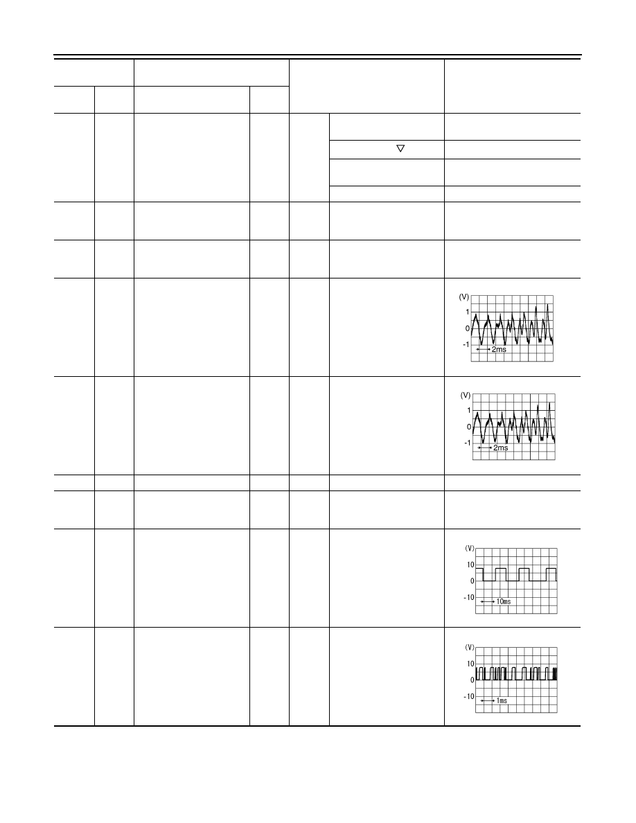
Terminal

(Wire color)

Description

Condition

Reference value

(Approx.)

+

–

Signal name

Input/

Output

SKIB3609E

SKIB3609E

SKIA9299J

SKIA9300J

AV

AV CONTROL UNIT

AV-97

< ECU DIAGNOSIS >

[MID AUDIO]

C

D

E

F

G

H

I

J

K

L

M

B

A

O

P

30

(L)

Ground

Communication signal
(CONT

→

SAT)

Output

Ignition 

switch 

ON

When satellite radio mode 
is selected

34

—

Antenna amp.

—

—

—

—

35

—

Antenna amp.

—

—

—

—

36

(G)

Ground

AUX image signal

Output

Ignition 

switch 

ON

When AUX mode is select-
ed

37

(R)

Ground

AUX image ground

—

Ignition 

switch 

ON

—

0V

38

(R)

Ground

RGB signal (B: blue)

Output

Ignition 

switch 

ON

Start confirmation/adjust-
ment mode, and then dis-
play color bar by selecting 
“Color Spectrum Bar” on 
DISPLAY DIAGNOSIS 
screen.

39

(B)

Ground

RGB signal (G: green)

Output

Ignition 

switch 

ON

Start confirmation/adjust-
ment mode, and then dis-
play color bar by selecting 
“Color Spectrum Bar” on 
DISPLAY DIAGNOSIS 
screen.

40

(W)

Ground

RGB signal (R: red)

Output

Ignition 

switch 

ON

Start confirmation/adjust-
ment mode, and then dis-
play color bar by selecting 
“Color Spectrum Bar” on 
DISPLAY DIAGNOSIS 
screen.

41

(R)

Ground

RGB synchronizing signal

Output

Ignition 

switch 

ON

—

Terminal

(Wire color)

Description

Condition

Reference value

(Approx.)

+

–

Signal name

Input/

Output

SKIA9301J

SKIB2251J

SKIB2237J

SKIB2236J

SKIB2238J

SKIB3603E

AV-98

< ECU DIAGNOSIS >

[MID AUDIO]

AV CONTROL UNIT

42

—

RGB synchronizing ground

—

Ignition 

switch 

ON

—

0V

43

(G)

Ground

RGB area (YS) signal

Output

Ignition 

switch 

ON

RGB image

5V

AUX image

44

(LG)

Ground

Communication signal
(DISP

→

CONT)

Input

Ignition 

switch 

ON

When adjusting display-
brightness

45

(B)

Ground

Horizontal synchronizing 
(HP) signal

Input

Ignition 

switch 

ON

—

46

(BR)

Ground

Signal ground

—

Ignition 

switch 

—

0V

47

(R)

Ground

Signal VCC

Output

Ignition 

switch 

ACC

—

9V

49

—

Shield

—

—

—

—

50

Ground

RGB ground

—

Ignition 

switch 

ON

—

0V

54

(B)

Ground

Ground

—

Ignition 
switch 
ON

—

0V

55

—

Shield

—

—

—

—

56

(V)

Ground

Communication signal
(CONT

→

DISP)

Output

Ignition 

switch 

ON

When adjusting display-
brightness

Terminal

(Wire color)

Description

Condition

Reference value

(Approx.)

+

–

Signal name

Input/

Output

PKIB4948J

PKIB5039J

SKIB3601E

PKIB5039J

AV

AV CONTROL UNIT

AV-99

< ECU DIAGNOSIS >

[MID AUDIO]

C

D

E

F

G

H

I

J

K

L

M

B

A

O

P

57

(W)

Ground

Vertical synchronizing (VP) 
signal

Input

Ignition 

switch 

On

—

58

(SB)

Ground

Inverter ground

—

Ignition 

switch 

ON

—

0V

59

(O)

Ground

Inverter VCC

Output

Ignition 

switch 

ACC

—

9V

64

Ground

Rear view camera video 
signal ground

—

Ignition 
switch 
ON

—

0V

65

(W)

Ground

Rear view camera video in 
(+)

Input

Ignition 
switch 
ON

With rear view camera ON

66

(G)

Ground

DVD player video signal (+)

Input

Ignition 

switch 

ON

With DVD player operating

68

(BR)

—

Rear view camera signal

Output

—

—

—

73

—

Shield

—

—

—

—

74

(R)

Ground

DVD player video ground

—

Ignition 

switch 

ON

—

0V

77

(B)

76

(R)

Headphone RH audio sig-
nal

Output

Ignition 
switch 
ON

With DVD player operating

Terminal

(Wire color)

Description

Condition

Reference value

(Approx.)

+

–

Signal name

Input/

Output

SKIB3598E

SKIB2251J

SKIB2251J

SKIA0177E

AV-100

< ECU DIAGNOSIS >

[MID AUDIO]

AV CONTROL UNIT

83

(R)

82

(G)

DVD player audio signal 
RH

Input

Ignition 
switch 
ON

With DVD player operating

85

(B)

Ground

Ground

—

Ignition 
switch 
ON

—

0V

86

(L)

—

CAN–H

Input/

Output

—

—

—

87

(P)

—

CAN–L

Input/

Output

—

—

—

88

(L)

—

AV communication signal 1 
(H)

Input/

Output

—

—

—

89

(P)

—

AV communication signal 1 
(L)

Input/

Output

—

—

—

90

(L)

—

AV communication signal 2 
(H)

Input/

Output

—

—

—

91

(P)

—

AV communication signal 2 
(L)

Input/

Output

—

—

—

93

(G)

92

(W)

Headphone LH audio sig-
nal

Output

Ignition 
switch 
ON

With DVD player operating

94

—

Shield

—

—

—

—

95

(G)

97

(Y)

AUX audio signal RH

Input

Ignition 

switch 

ON

When AUX mode is select-
ed

96

(L)

97

(Y)

AUX audio signal LH

Input

Ignition 

switch 

ON

When AUX mode is select-
ed

Terminal

(Wire color)

Description

Condition

Reference value

(Approx.)

+

–

Signal name

Input/

Output

SKIB3609E

SKIB3609E

SKIB3609E

SKIB3609E

AV

AV CONTROL UNIT

AV-101

< ECU DIAGNOSIS >

[MID AUDIO]

C

D

E

F

G

H

I

J

K

L

M

B

A

O

P

98

(B)

99

(W)

DVD player audio signal LH

Input

Ignition 

switch 

ON

With DVD player operating

100

—

Shield

—

—

—

—

101

(GR)

Ground

A/C and AV switch assem-
bly ground

—

Ignition 

switch 

ON

—

0V

103

(SB)

Ground

CD eject signal

Input

—

Pressing the eject switch

0V

Except for above

3.3V

104

(W/G)

Ground

Ignition signal

Input

Ignition 

switch 

ON

—

Battery voltage

105
(W)

Ground

Reverse signal

Input

Ignition 

switch 

ON

R position

12V

Other than R position

0V

106

(G)

Ground

Parking brake signal

Input

Ignition 

switch 

ON

Parking brake ON

0V

Parking brake OFF

12V

107

(LG)

Ground

Vehicle speed signal
 (8-pulse)

Input

Ignition 

switch 

ON

When vehicle speed is ap-
prox. 40 km/h (25MPH)

Terminal

(Wire color)

Description

Condition

Reference value

(Approx.)

+

–

Signal name

Input/

Output

SKIB3609E

SKIA6649J

AV-102

< ECU DIAGNOSIS >

[MID AUDIO]

AV CONTROL UNIT

Wiring Diagram

INFOID:0000000001450831

ALNWA0053GB

AV

AV CONTROL UNIT

AV-103

< ECU DIAGNOSIS >

[MID AUDIO]

C

D

E

F

G

H

I

J

K

L

M

B

A

O

P

ALNWA0054GB


Content      ..     30      31      32      33     ..