Nissan Pathfinder (2007 year). Instruction - part 155
 

  Index      Instructions     Nissan Pathfinder (2007 year) - Service and Repair Instruction


Search            copyright infringement  


Content      ..     153      154      155      156     ..


Nissan Pathfinder (2007 year). Instruction - part 155


TROUBLE DIAGNOSIS

EC-107

C

D

E

F

G

H

I

J

K

L

M

A

EC

2007 Pathfinder

13

G

Crankshaft position sensor 
(POS)

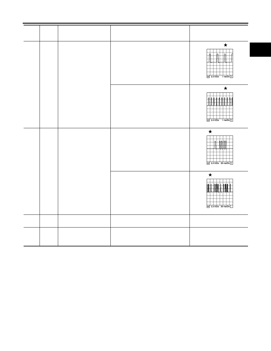
[Engine is running]

●

Warm-up condition

●

Idle speed

NOTE:
The pulse cycle changes depending on 
rpm at idle

Approximately 10V

[Engine is running]

●

Engine speed: 2,000 rpm

Approximately 10V

14

Y

Camshaft position sensor 
(PHASE) (Bank 2)

[Engine is running]

●

Warm-up condition

●

Idle speed

NOTE:
The pulse cycle changes depending on 
rpm at idle

1.0 - 4.0V

[Engine is running]

●

Engine speed: 2,000 rpm

1.0 - 4.0V

15

W

Knock sensor 
(Bank 1)

[Engine is running]

●

Idle speed

Approximately 2.5V

16

BR

A/F sensor 1 (Bank 2)

[Engine is running]

●

Warm-up condition

●

Engine speed: 2,000 rpm

Approximately 1.8V
Output voltage varies with air 
fuel ratio.

TER-

MINAL 

NO.

WIRE 

COLOR

ITEM

CONDITION

DATA (DC Voltage)

PBIB1041E

PBIB1042E

PBIB1039E

PBIB1040E

EC-108

TROUBLE DIAGNOSIS

2007 Pathfinder

21
22
23

W
LG
SB

Fuel injector No. 5
Fuel injector No. 3
Fuel injector No. 1

[Engine is running]

●

Warm-up condition

●

Idle speed

NOTE:
The pulse cycle changes depending on 
rpm at idle

BATTERY VOLTAGE

(11 - 14V)

[Engine is running]

●

Warm-up condition

●

Engine speed: 2,000 rpm

BATTERY VOLTAGE

(11 - 14V)

24
43

G
G

A/F sensor 1 heater (Bank 2)

[Engine is running]

●

Warm-up condition

●

Idle speed
(More than 140 seconds after starting 
engine)

Approximately 2.9 - 8.8V

25

P

Heated oxygen sensor 2 
heater (Bank 1)

[Engine is running]

●

Engine speed: Below 3,600 rpm after the 
following conditions are met

–

Engine: After warming up

–

Keeping the engine speed between 3,500 
and 4,000 rpm for 1 minute and at idle for 1 
minute under no load

0 - 1.0V

[Ignition switch: ON]

●

Engine: Stopped

[Engine is running]

●

Engine speed: Above 3,600 rpm

BATTERY VOLTAGE
(11 - 14V)

29

G

VIAS control solenoid valve

[Engine is running]

●

Idle speed

BATTERY VOLTAGE
(11 - 14V)

[Engine is running]

●

Engine speed: Between 2,200 and 3,300 
rpm

0 - 1.0V

32

W

EVAP control system pres-
sure sensor

[Ignition switch: ON]

Approximately 1.8 - 4.8V

TER-

MINAL 

NO.

WIRE 

COLOR

ITEM

CONDITION

DATA (DC Voltage)

SEC984C

SEC985C

PBIA8148J

TROUBLE DIAGNOSIS

EC-109

C

D

E

F

G

H

I

J

K

L

M

A

EC

2007 Pathfinder

33

L

Camshaft position sensor 
(PHASE) (Bank 1)

[Engine is running]

●

Warm-up condition

●

Idle speed

NOTE:
The pulse cycle changes depending on 
rpm at idle

1.0 - 4.0V

[Engine is running]

●

Engine speed: 2,000 rpm

1.0 - 4.0V

34

BR

Intake air temperature sen-
sor

[Engine is running]

Approximately 0 - 4.8V
Output voltage varies with intake 
air temperature.

35

O

A/F sensor 1 (Bank 1)

[Engine is running]

●

Warm-up condition

●

Engine speed: 2,000 rpm

Approximately 1.8V
Output voltage varies with air 
fuel ratio.

36

W

Knock sensor
(Bank 2)

[Engine is running]

●

Idle speed

Approximately 2.5V

40
41
42

V
R
O

Fuel injector No. 6
Fuel injector No. 4 
Fuel injector No. 2

[Engine is running]

●

Warm-up condition

●

Idle speed

NOTE:
The pulse cycle changes depending on 
rpm at idle

BATTERY VOLTAGE

(11 - 14V)

[Engine is running]

●

Warm-up condition

●

Engine speed: 2,000 rpm

BATTERY VOLTAGE

(11 - 14V)

TER-

MINAL 

NO.

WIRE 

COLOR

ITEM

CONDITION

DATA (DC Voltage)

PBIB1039E

PBIB1040E

SEC984C

SEC985C

EC-110

TROUBLE DIAGNOSIS

2007 Pathfinder

45

R

EVAP canister purge volume 
control solenoid valve

[Engine is running]

●

Idle speed

●

Accelerator pedal is not depressed even 
slightly, after engine starting

BATTERY VOLTAGE

(11 - 14V)

[Engine is running]

●

Engine speed: About 2,000 rpm (More than 
100 seconds after starting engine)

BATTERY VOLTAGE

(11 - 14V)

47

L

Sensor power supply (Throt-
tle position sensor)

[Ignition switch: ON]

Approximately 5V

48

SB

Sensor power supply
(EVAP control system pres-
sure sensor)

[Ignition switch: ON]

Approximately 5V

49

P

Sensor power supply
(Refrigerant pressure sen-
sor/Battery current sensor)

[Ignition switch: ON]

Approximately 5V

50

W

Throttle position sensor 1

[Ignition switch: ON]

●

Engine: Stopped

●

Shift lever: D

●

Accelerator pedal: Fully released

More than 0.36V

[Ignition switch: ON]

●

Engine: Stopped

●

Shift lever: D

●

Accelerator pedal: Fully depressed

Less than 4.75V

51

P

Mass air flow sensor

[Engine is running]

●

Warm-up condition

●

Idle speed

0.9 - 1.2V

[Engine is running]

●

Warm-up condition

●

Engine speed: 2,500 rpm

1.5 - 1.8V

55

G

Heated oxygen sensor 2 
(Bank 2)

[Engine is running]

●

Revving engine from idle to 3,000 rpm 
quickly after the following conditions are 
met

–

Engine: After warming up

–

Keeping the engine speed between 3,500 
and 4,000 rpm for 1 minute and at idle for 1 
minute under no load

0 - Approximately 1.0V

56

LG

A/F sensor 1 (Bank 1)

[Ignition switch: ON]

Approximately 2.2V

TER-

MINAL 

NO.

WIRE 

COLOR

ITEM

CONDITION

DATA (DC Voltage)

SEC990C

SEC991C

TROUBLE DIAGNOSIS

EC-111

C

D

E

F

G

H

I

J

K

L

M

A

EC

2007 Pathfinder

60
61
62

SB
L
Y

Ignition signal No. 5
Ignition signal No. 3
Ignition signal No. 1

[Engine is running]

●

Warm-up condition

●

Idle speed

NOTE:
The pulse cycle changes depending on 
rpm at idle

0 - 0.2V

[Engine is running]

●

Warm-up condition

●

Engine speed: 2,500 rpm

0.1 - 0.4V

66

B

Sensor ground
(Throttle position sensor)

[Engine is running]

●

Warm-up condition

●

Idle speed

Approximately 0V

67

B

Sensor ground

[Engine is running]

●

Warm-up condition

●

Idle speed

Approximately 0V

68

G

Sensor power supply
(Power steering pressure 
sensor)

[Ignition switch: ON]

Approximately 5V

69

R

Throttle position sensor 2

[Ignition switch: ON]

●

Engine: Stopped

●

Shift lever: D

●

Accelerator pedal: Fully released

Less than 4.75V

[Ignition switch: ON]

●

Engine: Stopped

●

Shift lever: D

●

Accelerator pedal: Fully depressed

More than 0.36V

70

BR

Refrigerant pressure sensor

[Engine is running]

●

Warm-up condition

●

Both A/C switch and blower switch: ON 
(Compressor operates)

1.0 - 4.0V

71

R

Battery current sensor

[Engine is running]

●

Battery: Fully charged*

●

Idle speed

Approximately 2.6 - 3.5V

73

Y

Engine coolant temperature 
sensor

[Engine is running]

Approximately 0 - 4.8V
Output voltage varies with 
engine coolant temperature.

74

W

Heated oxygen sensor 2 
(Bank 1)

[Engine is running]

●

Revving engine from idle to 3,000 rpm 
quickly after the following conditions are 
met

–

Engine: After warming up

–

Keeping the engine speed between 3,500 
and 4,000 rpm for 1 minute and at idle for 1 
minute under no load

0 - Approximately 1.0V

TER-

MINAL 

NO.

WIRE 

COLOR

ITEM

CONDITION

DATA (DC Voltage)

SEC986C

SEC987C

EC-112

TROUBLE DIAGNOSIS

2007 Pathfinder

75

P

A/F sensor 1 (Bank 2)

[Ignition switch: ON]

Approximately 2.2V

78

GR

Sensor ground
(Heated oxygen sensor 2)

[Engine is running]

●

Warm-up condition

●

Idle speed

Approximately 0V

79
80
81

P
GR
G

Ignition signal No. 6
Ignition signal No. 4
Ignition signal No. 2

[Engine is running]

●

Warm-up condition

●

Idle speed

NOTE:
The pulse cycle changes depending on 
rpm at idle

0 - 0.2V

[Engine is running]

●

Warm-up condition

●

Engine speed: 2,500 rpm

0.1 - 0.4V

82

B

Sensor ground
(APP sensor 1)

[Engine is running]

●

Warm-up condition

●

Idle speed

Approximately 0V

83

B

Sensor ground
(APP sensor 2)

[Engine is running]

●

Warm-up condition

●

Idle speed

Approximately 0V

85

W

Data link connector

[Ignition switch: ON]

●

CONSULT-II or GST: disconnected

Approximately 5V - Battery volt-
age (11 - 14V)

86

P

CAN communication line

[Ignition switch: ON]

Approximately 1.1 - 2.3V
Output voltage varies with the 
communication status.

90

L

Sensor power supply
(APP sensor 1)

[Ignition switch: ON]

Approximately 5V

91

G

Sensor power supply
(APP sensor 2)

[Ignition switch: ON]

Approximately 5V

94

L

CAN communication line

[Ignition switch: ON]

Approximately 2.6 - 3.2V
Output voltage varies with the 
communication status.

98

GR

Accelerator pedal position 
sensor 2

[Ignition switch: ON]

●

Engine: Stopped

●

Accelerator pedal: Fully released

0.28 - 0.48V

[Ignition switch: ON]

●

Engine: Stopped

●

Accelerator pedal: Fully depressed

More than 2.0

TER-

MINAL 

NO.

WIRE 

COLOR

ITEM

CONDITION

DATA (DC Voltage)

SEC986C

SEC987C

TROUBLE DIAGNOSIS

EC-113

C

D

E

F

G

H

I

J

K

L

M

A

EC

2007 Pathfinder

99

SB

ASCD steering switch

[Ignition switch: ON]

●

ASCD steering switch: OFF

Approximately 4V

[Ignition switch: ON]

●

MAIN switch: Pressed

Approximately 0V

[Ignition switch: ON]

●

CANCEL switch: Pressed

Approximately 1V

[Ignition switch: ON]

●

RESUME/ACCELERATE switch: Pressed

Approximately 3V

[Ignition switch: ON]

●

SET/COAST switch: Pressed

Approximately 2V

101

LG

Stop lamp switch

[Ignition switch: OFF]

●

Brake pedal: Fully released

Approximately 0V

[Ignition switch: OFF]

●

Brake pedal: Slightly depressed

BATTERY VOLTAGE
(11 - 14V)

102

G

PNP switch

[Ignition switch: ON]

●

Shift lever: P or N

Approximately 0V

[Ignition switch: ON]

●

Except above position

BATTERY VOLTAGE
(11 - 14V)

104

O

Throttle control motor relay

[Ignition switch: OFF]

BATTERY VOLTAGE
(11 - 14V)

[Ignition switch: ON]

0 - 1.0V

106

R

Accelerator pedal position 
sensor 1

[Ignition switch: ON]

●

Engine: Stopped

●

Accelerator pedal: Fully released

0.65 - 0.87V

[Ignition switch: ON]

●

Engine: Stopped

●

Accelerator pedal: Fully depressed

More than 4.3V

107

Y

Fuel tank temperature sen-
sor

[Engine is running]

Approximately 0 - 4.8V
Output voltage varies with fuel 
tank temperature.

108

LG

ASCD brake switch

[Ignition switch: ON]

●

Brake pedal: Slightly depressed

Approximately 0V

[Ignition switch: ON]

●

Brake pedal: Fully released

BATTERY VOLTAGE
(11 - 14V)

109

W/R

Ignition switch

[Ignition switch: OFF]

0V

[Ignition switch: ON]

BATTERY VOLTAGE
(11 - 14V)

111

BR

ECM relay
(Self shut-off)

[Engine is running]
[Ignition switch: OFF]

●

For a few seconds after turning ignition 
switch OFF

0 - 1.5V

[Ignition switch: OFF]

●

More than a few seconds after turning igni-
tion switch OFF

BATTERY VOLTAGE
(11 - 14V)

TER-

MINAL 

NO.

WIRE 

COLOR

ITEM

CONDITION

DATA (DC Voltage)

EC-114

TROUBLE DIAGNOSIS

2007 Pathfinder

: Average voltage for pulse signal (Actual pulse signal can be confirmed by oscilloscope.)

*: Before measuring the terminal voltage, confirm that the battery is fully charged. Refer to 

SC-5, "SPECIFIC GRAVITY CHECK"

 .

CONSULT-II Function (ENGINE)

UBS00K4C

FUNCTION

*: The following emission-related diagnostic information is cleared when the ECM memory is erased.

●

Diagnostic trouble codes

●

1st trip diagnostic trouble codes

●

Freeze frame data

●

1st trip freeze frame data

●

System readiness test (SRT) codes

●

Test values

113

V

Fuel pump relay

[Ignition switch: ON]

●

For 1 second after turning ignition switch 
ON

[Engine is running]

0 - 1.5V

[Ignition switch: ON]

●

More than 1 second after turning ignition 
switch ON

BATTERY VOLTAGE
(11 - 14V)

115
116

B
GR

ECM ground

[Engine is running]

●

Idle speed

Body ground

117

G

EVAP canister vent control 
valve

[Ignition switch: ON]

BATTERY VOLTAGE
(11 - 14V)

119
120

R
P

Power supply for ECM

[Ignition switch: ON]

BATTERY VOLTAGE
(11 - 14V)

121

R/B

Power supply for ECM 
(Back-up)

[Ignition switch: OFF]

BATTERY VOLTAGE
(11 - 14V)

TER-

MINAL 

NO.

WIRE 

COLOR

ITEM

CONDITION

DATA (DC Voltage)

Diagnostic test mode

Function

Work support

This mode enables a technician to adjust some devices faster and more accurately by following the 
indications on the CONSULT-II unit.

Self-diagnostic results

Self-diagnostic results such as 1st trip DTC, DTCs and 1st trip freeze frame data or freeze frame data 
can be read and erased quickly.*

Data monitor

Input/Output data in the ECM can be read.

Data monitor (SPEC)

Input/Output of the specification for Basic fuel schedule, AFM, A/F feedback control value and the 
other data monitor items can be read.

CAN diagnostic support 
monitor

The results of transmit/receive diagnosis of CAN communication can be read.

Active test

Diagnostic Test Mode in which CONSULT-II drives some actuators apart from the ECMs and also 
shifts some parameters in a specified range.

Function test

This mode is used to inform customers when their vehicle condition requires periodic maintenance.

DTC & SRT confirmation

The status of system monitoring tests and the self-diagnosis status/result can be confirmed.

ECM part number

ECM part number can be read.


Content      ..     153      154      155      156     ..