Nissan Pathfinder (2006 year). Instruction - part 308
HEADLAMP (FOR USA)
LT-19
C
D
E
F
G
H
I
J
L
M
A
B
LT
2006 Pathfinder
5.
CHECK HEADLAMP CIRCUIT
1.
Turn ignition switch OFF.
2.
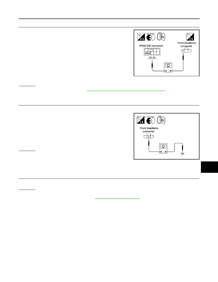
Disconnect IPDM E/R connector.
3.
Check continuity between IPDM E/R harness connector E123
terminal 56 and front headlamp RH harness connector E107 ter-
minal 1.
4.
Check continuity between IPDM E/R harness connector E123
terminal 55 and front headlamp LH harness connector E11 ter-
minal 1.
OK or NG
OK
>> Replace IPDM E/R. Refer to
PG-32, "Removal and Installation of IPDM E/R"
NG
>> Repair harness or connector.
6.
CHECK HEADLAMP GROUND
1.
Turn ignition switch OFF.
2.
Check continuity between front headlamp RH harness connec-
tor E107 terminal 2 and ground.
3.
Check continuity between front headlamp LH harness connector
E11 terminal 2 and ground.
OK or NG
OK
>> Check front headlamp connector for damage or poor
connection. Repair as necessary.
NG
>> Repair harness or connector.
Headlamp HI Does Not Illuminate (One Side)
EKS00FUB
1.
BULB INSPECTION
Inspect inoperative headlamp bulb.
OK or NG
OK
>> GO TO 2.
NG
>> Replace headlamp bulb. Refer to
56 - 1
: Continuity should exist.
55 - 1
: Continuity should exist.
WKIA3498E
2 - Ground
: Continuity should exist.
2 - Ground
: Continuity should exist.
WKIA3499E