Nissan Pathfinder (2006 year). Instruction - part 221
ASCD BRAKE SWITCH
EC-627
C
D
E
F
G
H
I
J
K
L
M
A
EC
2006 Pathfinder
11.
CHECK INTERMITTENT INCIDENT
Refer to
EC-144, "TROUBLE DIAGNOSIS FOR INTERMITTENT INCIDENT"
>> INSPECTION END
Component Inspection
UBS00KIT
ASCD BRAKE SWITCH
1.
Turn ignition switch OFF.
2.
Disconnect ASCD brake switch harness connector.
3.
Check harness continuity between ASCD brake switch terminals
1 and 2 under the following conditions.
If NG, adjust ASCD brake switch installation, refer to
, and perform step 3 again.
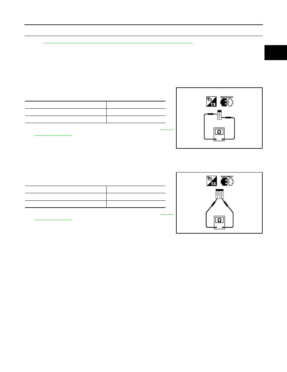
STOP LAMP SWITCH
1.
Turn ignition switch OFF.
2.
Disconnect stop lamp switch harness connector.
3.
Check harness continuity between stop lamp switch terminals 1
and 2 under the following conditions.
If NG, adjust stop lamp switch installation, refer to
, and perform step 3 again.
Condition
Continuity
When brake pedal: Fully released.
Should exist.
When brake pedal: Slightly depressed.
Should not exist.
SEC023D
Condition
Continuity
When brake pedal: Fully released.
Should not exist.
When brake pedal: Slightly depressed.
Should exist.
PBIB1185E