Nissan Pathfinder (2006 year). Instruction - part 214
DTC P2101 ELECTRIC THROTTLE CONTROL FUNCTION
EC-571
C
D
E
F
G
H
I
J
K
L
M
A
EC
2006 Pathfinder
Specification data are reference values and are measured between each terminal and ground.
Pulse signal is measured by CONSULT-II.
CAUTION:
Do not use ECM ground terminals when measuring input/output voltage. Doing so may result in dam-
age to the ECM's transistor. Use a ground other than ECM terminals, such as the ground.
: Average voltage for pulse signal (Actual pulse signal can be confirmed by oscilloscope.)
Diagnostic Procedure
UBS00KC9
1.
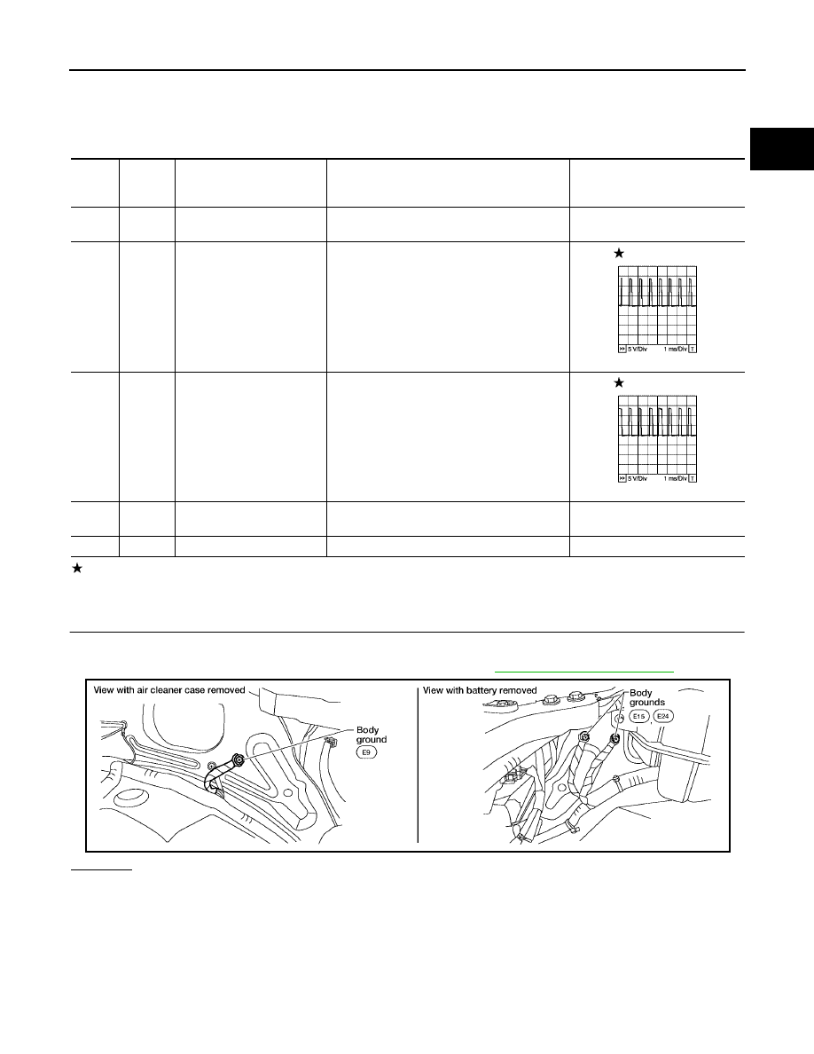
CHECK GROUND CONNECTIONS
1.
Turn ignition switch OFF
2.
Loosen and retighten three ground screws on the body. Refer to
.
OK or NG
OK
>> GO TO 2.
NG
>> Repair or replace ground connections.
TER-
MINAL
NO.
WIRE
COLOR
ITEM
CONDITION
DATA (DC Voltage)
3
V
Throttle control motor relay
power supply
[Ignition switch: ON]
BATTERY VOLTAGE
(11 - 14V)
4
L/W
Throttle control motor
(Close)
[Ignition switch: ON]
●
Engine: Stopped
●
Shift lever: D
●
Accelerator pedal: Fully released
0 - 14V
5
L/B
Throttle control motor
(Open)
[Ignition switch: ON]
●
Engine: Stopped
●
Shift lever: D
●
Accelerator pedal: Fully depressed
0 - 14V
104
O
Throttle control motor relay
[Ignition switch: OFF]
BATTERY VOLTAGE
(11 - 14V)
[Ignition switch: ON]
0 - 1.0V
PBIB1104E
PBIB1105E
BBIA0539E