Nissan Pathfinder (2006 year). Instruction - part 30
 

  Index      Instructions     Nissan Pathfinder (2006 year) - Service and Repair Instruction


Search            copyright infringement  


Content      ..     28      29      30      31     ..


Nissan Pathfinder (2006 year). Instruction - part 30


ON-VEHICLE SERVICE

AT-231

D

E

F

G

H

I

J

K

L

M

A

B

AT

2006 Pathfinder

ON-VEHICLE SERVICE

PFP:00000

Oil Pan

ECS00ELT

REMOVAL AND INSTALLATION
Removal

1.

Drain A/T fluid. Refer to 

MA-24, "Changing the Automatic Transmission Fluid (ATF)"

 .

2.

Remove oil pan and gasket.

3.

Check for foreign materials in oil pan to help determine cause of malfunction. If the A/T fluid is very dark,
has some burned smell, or contains foreign particles then friction material (clutches, band) may need
replacement. A tacky film that will not wipe clean indicates varnish build up. Varnish can cause valves,
servo, and clutches to stick and can inhibit pump pressure.

CAUTION:

If friction material is detected, flush the transmission cooler after repair. Refer to 

AT-15, "A/T Fluid

Cooler Cleaning"

 .

4.

Remove magnets from oil pan.

Installation

1.

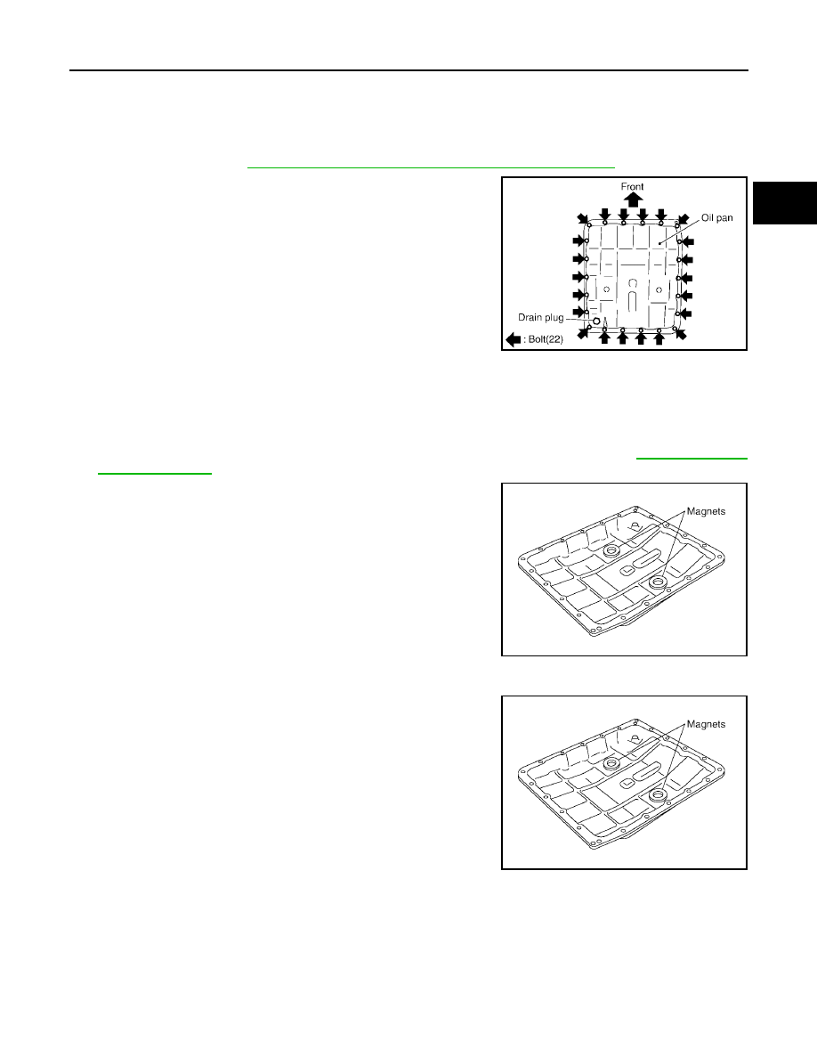
Install the oil pan magnets as shown.

SCIA2308E

SCIA5200E

SCIA5200E

AT-232

ON-VEHICLE SERVICE

2006 Pathfinder

2.

Install the oil pan and new oil pan gasket.

CAUTION:

●

Be sure the oil drain plug is located to the rear of the
transmission assembly.

●

Before installing oil pan bolts, remove any traces of old
sealant from the sealing surfaces and threaded holes.

●

Do not reuse old gasket, replace with a new one.

●

Always replace the oil pan bolts as they are self-sealing.

●

Partially install the oil pan bolts in a criss-cross pattern to
prevent dislocation of the gasket.

3.

Tighten oil pan bolts in numerical order as shown.

4.

Install drain plug to oil pan and tighten to specification.

CAUTION:

Do not reuse old drain plug gasket replace with a new one.

5.

Refill the A/T with fluid and check for fluid leakage. Refer to 

MA-24, "Changing the Automatic Transmis-

sion Fluid (ATF)"

 .

SCIA2308E

Oil pan bolts

: 7.9 N·m (0.81 kg-m, 70 in-lb)

SCIA4113E

Drain plug

: 34 N·m (3.5 kg-m, 25 ft-lb)

ON-VEHICLE SERVICE

AT-233

D

E

F

G

H

I

J

K

L

M

A

B

AT

2006 Pathfinder

Control Valve With TCM and A/T Fluid Temperature Sensor 2

ECS00ELU

COMPONENTS

1.

Transmission

2.

Snap ring

3.

Sub-harness

4.

Control valve with TCM

5.

Bracket

6.

A/T fluid temperature sensor 2

7.

Oil pan gasket

8.

Oil pan

9.

Magnet

10. Drain plug

11.

Drain plug gasket

12. Oil pan bolt

13. Terminal cord assembly

14. O-ring

SCIA5478E

AT-234

ON-VEHICLE SERVICE

2006 Pathfinder

CONTROL VALVE WITH TCM REMOVAL AND INSTALLATION
Removal

1.

Disconnect negative battery terminal.

2.

Drain A/T fluid. Refer to 

MA-24, "Changing the Automatic Transmission Fluid (ATF)"

 .

3.

Disconnect A/T assembly harness connector.

4.

Remove snap ring from A/T assembly harness connector.

5.

Push A/T assembly harness connector.

CAUTION:

Be careful not to damage connector.

6.

Remove oil pan and oil pan gasket. Refer to 

AT-231, "Removal"

 .

7.

Straighten the terminal clip to free the terminal cord assembly for
A/T fluid temperature sensor 2 harness.

8.

Disconnect A/T fluid temperature sensor 2 connector.

CAUTION:

Be careful not to damage connector.

9.

Straighten terminal clips to free revolution sensor harness.

10. Disconnect revolution sensor connector.

CAUTION:

Be careful not to damage connector.

SCIA5021E

SCIA5022E

SCIA5446E

SCIA7022E

ON-VEHICLE SERVICE

AT-235

D

E

F

G

H

I

J

K

L

M

A

B

AT

2006 Pathfinder

11. Remove bolts A, B and C from control valve with TCM.

12. Remove control valve with TCM from transmission case.

CAUTION:

When removing, be careful with the instruction valve notch and
instruction plate height. Remove it vertically.

13. Remove A/T fluid temperature sensor 2 with bracket from con-

trol valve with TCM.

14. Remove bracket from A/T fluid temperature sensor 2.

15. Remove O-ring from A/T assembly harness connector.

Bolt symbol

Length mm (in)

Number of bolts

A

42 (1.65)

5

B

55 (2.17)

6

C

40 (1.57)

1

SCIA5139E

SCIA5142E

SCIA5301E

SCIA5264E

SCIA5155E

AT-236

ON-VEHICLE SERVICE

2006 Pathfinder

16. Disconnect TCM connectors.

CAUTION:

Be careful not to damage connectors.

17. Remove A/T assembly harness connector from control valve

with TCM using suitable tool.

18. Disconnect TCM connector and park/neutral position switch

connector

CAUTION:

Be careful not to damage connectors.

SCIA5447E

SCIA5448E

SCIA5449E

ON-VEHICLE SERVICE

AT-237

D

E

F

G

H

I

J

K

L

M

A

B

AT

2006 Pathfinder

Installation

1.

Connect TCM connector and park/neutral position switch con-
nector.

2.

Install A/T assembly harness connector to control valve with
TCM.

3.

Connect TCM connector.

4.

Install new O-ring in A/T assembly harness connector.

CAUTION:

●

Do not reuse O-ring.

●

Apply ATF to O-ring.

SCIA5449E

SCIA5450E

SCIA5447E

SCIA5155E

AT-238

ON-VEHICLE SERVICE

2006 Pathfinder

5.

Install A/T fluid temperature sensor 2 to bracket.

6.

Install A/T fluid temperature sensor 2 (with bracket) in control
valve with TCM. Tighten A/T fluid temperature sensor 2 bolt to
the specified torque. Refer to 

AT-233, "COMPONENTS"

 .

CAUTION:

Adjust bolt hole of bracket to bolt hole of control valve with
TCM.

7.

Install control valve with TCM in transmission case.

CAUTION:

●

Make sure that turbine revolution sensor is securely
installed into turbine revolution sensor hole.

●

Hang down revolution sensor harness toward outside so
as not to disturb installation of control valve with TCM.

●

Adjust A/T assembly harness connector of control valve
with TCM to terminal hole of transmission case.

●

Assemble it so that instruction valve cutout is engaged with
instruction plate projection.

SCIA5264E

SCIA5301E

SCIA5034E

SCIA5142E


Content      ..     28      29      30      31     ..