Nissan Pathfinder (2005 year). Instruction - part 434
TROUBLE DIAGNOSIS FOR SYSTEM
TF-91
[ATX14B]
C
E
F
G
H
I
J
K
L
M
A
B
TF
2005 Pathfinder
4.
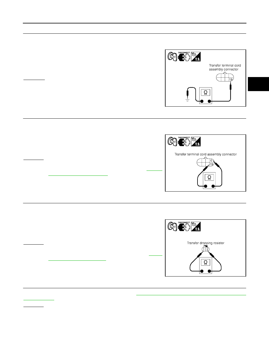
CHECK GROUND CIRCUIT
1.
Turn ignition switch “OFF”. (Stay for at least 5 seconds.)
2.
Disconnect transfer terminal cord assembly harness connector.
3.
Check continuity between transfer terminal cord assembly har-
ness connector F56 terminal 19 and ground.
Also check harness for short to power.
OK or NG
OK
>> GO TO 5.
NG
>> Repair open circuit or short to power in harness or con-
nectors.
5.
CHECK CLUTCH PRESSURE SOLENOID
1.
Turn ignition switch “OFF”. (Stay for at least 5 seconds.)
2.
Disconnect transfer terminal cord assembly harness connector.
3.
Check resistance between transfer terminal cord assembly har-
ness connector F56 terminals 6 and 19.
OK or NG
OK
>> GO TO 6.
NG
>> Replace clutch pressure solenoid. Refer to
.
6.
CHECK TRANSFER DROPPING RESISTOR
1.
Turn ignition switch “OFF”. (Stay for at least 5 seconds.)
2.
Disconnect transfer dropping resistor harness connector.
3.
Check resistance between transfer dropping resistor terminals 1
and 2.
OK or NG
OK
>> GO TO 7.
NG
>> Replace transfer dropping resistor.
Refer to
"Location of Electrical Parts"
.
7.
CHECK TRANSFER CONTROL UNIT
Check transfer control unit input/output signal. Refer to
TF-38, "Transfer Control Unit Input/Output Signal Ref-
.
OK or NG
OK
>> GO TO 8.
NG
>> Check transfer control unit pin terminals for damage or loose connection with harness connector.
If any items are damaged, repair or replace damaged parts.
Continuity should exist.
SDIA2723E
6 - 19
: Approx. 3.0 - 3.4
Ω
SDIA2724E
1 - 2
: Approx. 11.2 - 12.8
Ω
SDIA2725E