Nissan Pathfinder (2005 year). Instruction - part 319
 

  Index      Instructions     Nissan Pathfinder (2005 year) - Service and Repair Instruction


Search            copyright infringement  


Content      ..     317      318      319      320     ..


Nissan Pathfinder (2005 year). Instruction - part 319


CAN SYSTEM (TYPE 7)

LAN-251

[CAN]

C

D

E

F

G

H

I

J

L

M

A

B

LAN

2005 Pathfinder

7.

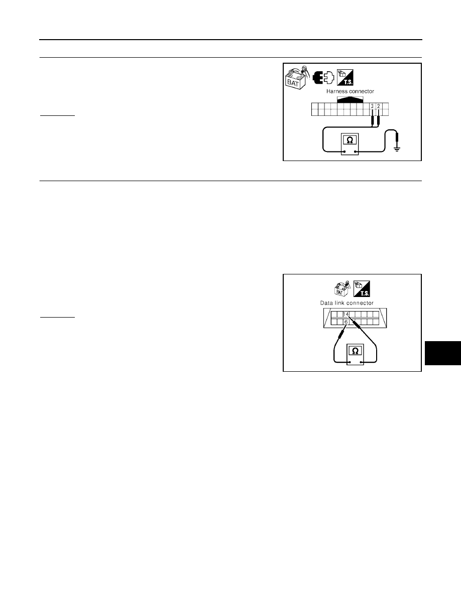
CHECK HARNESS FOR SHORT CIRCUIT

Check continuity between harness connector E5 terminals 2 (L), 3
(P) and ground.

OK or NG

OK

>> GO TO 8.

NG

>> Repair harness between harness connector E5 and har-

ness connector E152.

8.

CHECK HARNESS FOR SHORT CIRCUIT

1.

Disconnect following connectors.

–

Front air control connector

–

Steering angle sensor connector

–

BCM connector

–

Combination meter connector

–

Transfer control unit connector

–

Harness connector M40

–

Harness connector M91

2.

Check continuity between data link connector M22 terminals 6
(L) and 14 (P).

OK or NG

OK

>> GO TO 9.

NG

>> Check the following harnesses. If any harness is dam-

aged, repair the harness.

●

Harness between data link connector and harness
connector M31

●

Harness between data link connector and front air
control

●

Harness between data link connector and steering angle sensor

●

Harness between data link connector and BCM

●

Harness between data link connector and combination meter

●

Harness between data link connector and transfer control unit

●

Harness between data link connector and harness connector M40

●

Harness between data link connector and harness connector M91

2 (L) – Ground

: Continuity should not exist.

3 (P) – Ground

: Continuity should not exist.

SKIB2817E

6 (L) – 14 (P)

: Continuity should not exist.

SKIA6868E

LAN-252

[CAN]

CAN SYSTEM (TYPE 7)

2005 Pathfinder

9.

CHECK HARNESS FOR SHORT CIRCUIT

Check continuity between data link connector M22 terminals 6 (L),
14 (P) and ground.

OK or NG

OK

>> GO TO 10.

NG

>> Check the following harnesses. If any harness is dam-

aged, repair the harness.

●

Harness between data link connector and harness
connector M31

●

Harness between data link connector and front air control

●

Harness between data link connector and steering angle sensor

●

Harness between data link connector and BCM

●

Harness between data link connector and combination meter

●

Harness between data link connector and transfer control unit

●

Harness between data link connector and harness connector M40

●

Harness between data link connector and harness connector M91

10.

CHECK HARNESS FOR SHORT CIRCUIT

1.

Disconnect following connectors.

–

Driver seat control unit connector

–

Harness connector P1

2.

Check continuity between driver seat control unit harness con-
nector P2 terminals 3 (L) and 19 (P).

OK or NG

OK

>> GO TO 11.

NG

>> Repair harness between driver seat control unit and har-

ness connector P1.

11.

CHECK HARNESS FOR SHORT CIRCUIT

Check continuity between driver seat control unit harness connector
P2 terminals 3 (L), 19 (P) and ground.

OK or NG

OK

>> GO TO 12.

NG

>> Repair harness between driver seat control unit and har-

ness connector P1.

6 (L) – Ground

: Continuity should not exist.

14 (P) – Ground

: Continuity should not exist.

PKIA9872E

3 (L) – 19 (P)

: Continuity should not exist.

PKIA6842E

3 (L) – Ground

: Continuity should not exist.

19 (P) – Ground

: Continuity should not exist.

SKIB2818E

CAN SYSTEM (TYPE 7)

LAN-253

[CAN]

C

D

E

F

G

H

I

J

L

M

A

B

LAN

2005 Pathfinder

12.

CHECK HARNESS FOR SHORT CIRCUIT

Check continuity between harness connector B37 terminals 15 (L)
and 14 (P).

OK or NG

OK

>> GO TO 13.

NG

>> Repair harness between harness connector B37 and

harness connector B69.

13.

CHECK HARNESS FOR SHORT CIRCUIT

Check continuity between harness connector B37 terminals 15 (L),
14 (P) and ground.

OK or NG

OK

>> GO TO 14.

NG

>> Repair harness between harness connector B37 and

harness connector B69.

14.

CHECK HARNESS FOR SHORT CIRCUIT

1.

Disconnect ABS actuator and electric unit (control unit) connector and IPDM E/R connector.

2.

Check continuity between IPDM E/R harness connector E122
terminals 39 (L) and 40 (P).

OK or NG

OK

>> GO TO 15.

NG

>> Check the following harnesses. If any harness is dam-

aged, repair the harness.

●

Harness between IPDM E/R and ABS actuator and
electric unit (control unit)

●

Harness between IPDM E/R and harness connector
E26

15 (L) – 14 (P)

: Continuity should not exist.

SKIB2819E

15 (L) – Ground

: Continuity should not exist.

14 (P) – Ground

: Continuity should not exist.

SKIB2820E

39 (L) – 40 (P)

: Continuity should not exist.

PKIA8141E

LAN-254

[CAN]

CAN SYSTEM (TYPE 7)

2005 Pathfinder

15.

CHECK HARNESS FOR SHORT CIRCUIT

Check continuity between IPDM E/R harness connector E122 termi-
nals 39 (L), 40 (P) and ground.

OK or NG

OK

>> GO TO 16.

NG

>> Check the following harnesses. If any harness is dam-

aged, repair the harness.

●

Harness between IPDM E/R and ABS actuator and
electric unit (control unit)

●

Harness between IPDM E/R and harness connector E26

16.

ECM AND IPDM E/R INTERNAL CIRCUIT INSPECTION

1.

Remove ECM and IPDM E/R from vehicle.

2.

Check resistance between ECM terminals 94 and 86.

3.

Check resistance between IPDM E/R terminals 39 and 40.

OK or NG

OK

>> GO TO 17.

NG

>> Replace ECM and/or IPDM E/R.

17.

CHECK SYMPTOM

1.

Fill in described symptoms on the column “Symptom” in the check sheet.

2.

Connect all connectors, and then make sure that the symptom is reproduced.

OK or NG

OK

>> GO TO 18.

NG

>> Refer to

LAN-15, "Example of Filling in Check Sheet When Initial Conditions Are Not Reproduced"

.

39 (L) – Ground

: Continuity should not exist.

40 (P) – Ground

: Continuity should not exist.

SKIB2821E

94 – 86

: Approx. 108 - 132

Ω

39 – 40

: Approx. 108 - 132

Ω

LKIA0037E

CAN SYSTEM (TYPE 7)

LAN-255

[CAN]

C

D

E

F

G

H

I

J

L

M

A

B

LAN

2005 Pathfinder

18.

UNIT REPRODUCIBILITY INSPECTION

Perform the following procedure for each unit, and then perform reproducibility test.

1.

Turn ignition switch OFF.

2.

Disconnect the battery cable from the negative terminal.

3.

Disconnect the unit connector.

4.

Connect the battery cable to the negative terminal.

5.

Make sure that the symptom filled in the “Symptom” of the check sheet is reproduced. (Do not confuse it
with the symptom related to removed unit.)

6.

Make sure that the same symptom is reproduced.

–

TCM

–

Front air control

–

Steering angle sensor

–

BCM

–

Combination meter

–

Transfer control unit

–

Driver seat control unit

–

ABS actuator and electric unit (control unit)

–

ECM

–

IPDM E/R

Inspection results

Reproduced>>Install removed unit, and then check the other unit.
Not reproduced>>Replace removed unit.

IPDM E/R Ignition Relay Circuit Inspection

UKS003DD

Check the following. If no malfunction is found, replace the IPDM E/R.

●

IPDM E/R power supply circuit. Refer to

PG-26, "IPDM E/R Power/Ground Circuit Inspection"

.

●

Ignition power supply circuit. Refer to

PG-14, "IGNITION POWER SUPPLY — IGNITION SW. IN ON

AND/OR START"

.

LAN-256

[CAN]

CAN SYSTEM (TYPE 8)

2005 Pathfinder

CAN SYSTEM (TYPE 8)

PFP:23710

System Description

UKS003B5

CAN (Controller Area Network) is a serial communication line for real time application. It is an on-vehicle mul-
tiplex communication line with high data communication speed and excellent error detection ability. Many elec-
tronic control units are equipped onto a vehicle, and each control unit shares information and links with other
control units during operation (not independent). In CAN communication, control units are connected with 2
communication lines (CAN H line, CAN L line) allowing a high rate of information transmission with less wiring.
Each control unit transmits/receives data but selectively reads required data only.

Component Parts and Harness Connector Location

UKS003B6

BKIA0107E

CAN SYSTEM (TYPE 8)

LAN-257

[CAN]

C

D

E

F

G

H

I

J

L

M

A

B

LAN

2005 Pathfinder

Schematic

UKS003B7

BKWA0366E

LAN-258

[CAN]

CAN SYSTEM (TYPE 8)

2005 Pathfinder

Wiring Diagram - CAN -

UKS003B8

BKWA0354E


Content      ..     317      318      319      320     ..