Nissan Pathfinder (2005 year). Instruction - part 196
DTC P1121 ELECTRIC THROTTLE CONTROL ACTUATOR
EC-419
C
D
E
F
G
H
I
J
K
L
M
A
EC
2005 Pathfinder
PROCEDURE FOR MALFUNCTION C
With CONSULT-II
1.
Turn ignition switch ON and wait at least 1 second.
2.
Select “DATA MONITOR” mode with CONSULT-II.
3.
Shift selector lever to D position and wait at least 3 seconds.
4.
Shift selector lever to P or N position.
5.
Start engine and let it idle for 3 seconds.
6.
If DTC is detected, go to
EC-419, "Diagnostic Procedure"
.
With GST
Follow the procedure “WITH CONSULT-II” above.
Diagnostic Procedure
UBS00KC4
1.
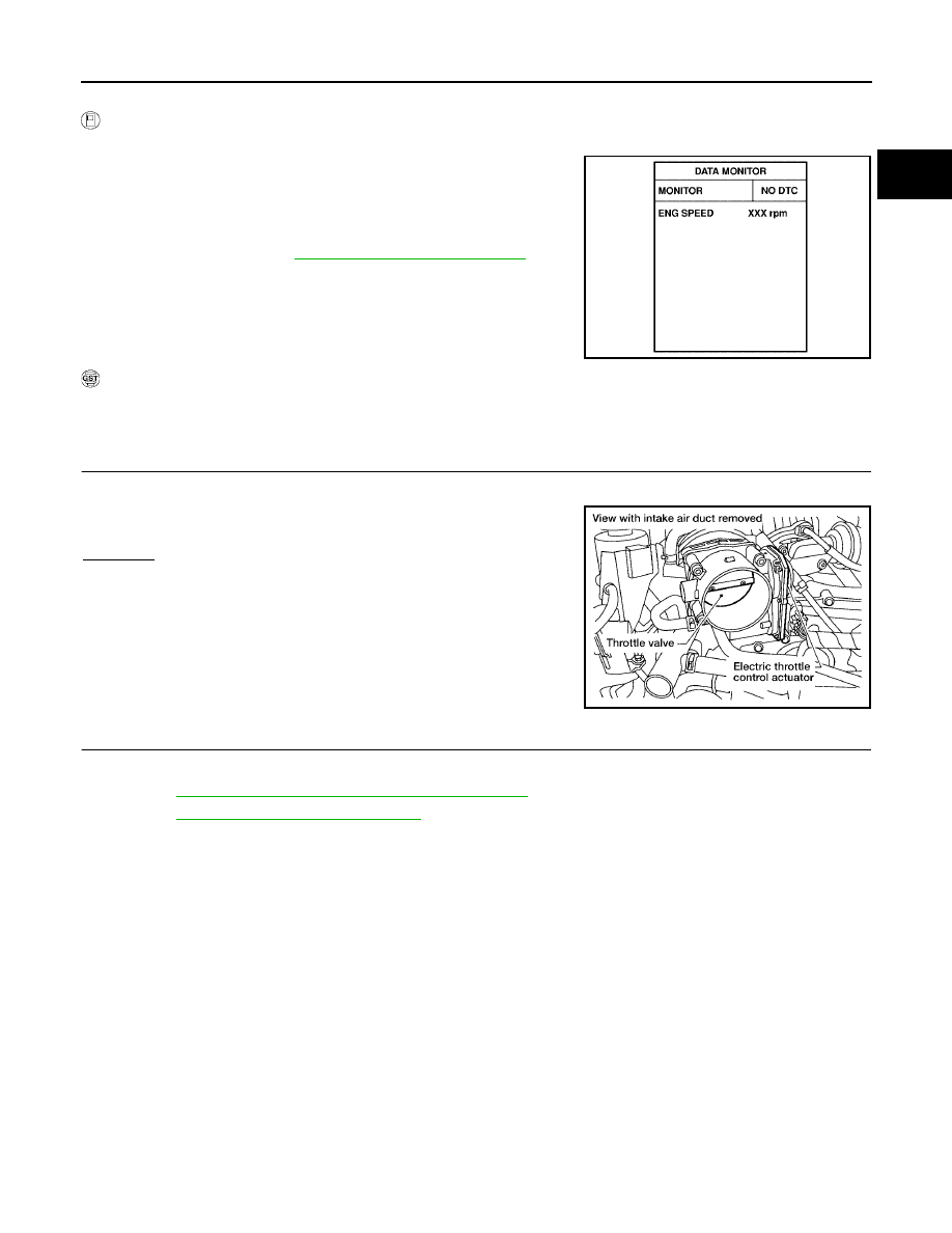
CHECK ELECTRIC THROTTLE CONTROL ACTUATOR VISUALLY
1.
Remove the intake air duct.
2.
Check if a foreign matter is caught between the throttle valve
and the housing.
OK or NG
OK
>> GO TO 2.
NG
>> Remove the foreign matter and clean the electric throttle
control actuator inside.
2.
REPLACE ELECTRIC THROTTLE CONTROL ACTUATOR
1.
Replace the electric throttle control actuator.
2.
Perform
EC-88, "Throttle Valve Closed Position Learning"
.
3.
Perform
EC-89, "Idle Air Volume Learning"
.
>> INSPECTION END
SEF058Y
BBIA0554E