Nissan Pathfinder (2005 year). Instruction - part 60
OPTICAL SENSOR
ATC-127
C
D
E
F
G
H
I
K
L
M
A
B
ATC
2005 Pathfinder
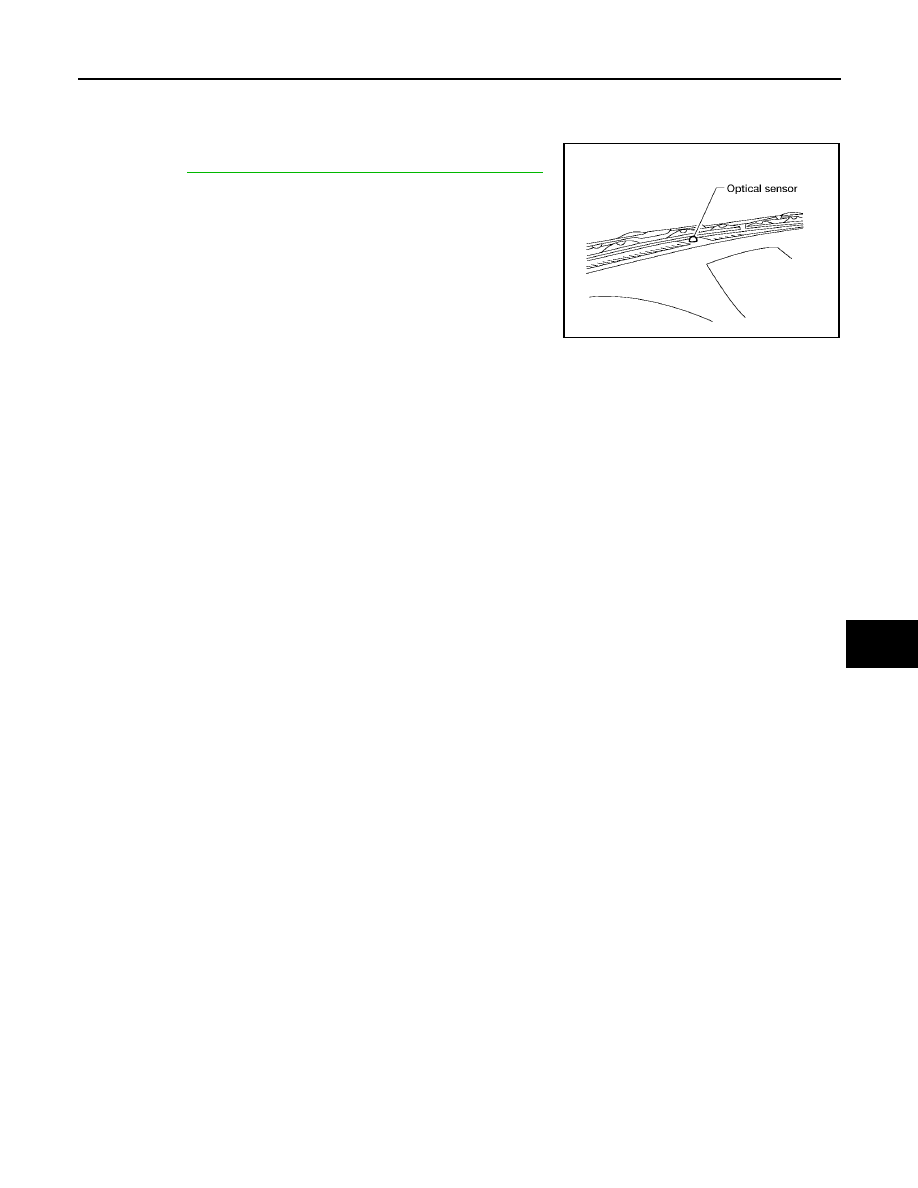
OPTICAL SENSOR
PFP:28576
Removal and Installation
EJS002XO
The optical sensor is located in the top center of the instrument
panel. Refer to
LT-62, "Removal and Installation of Optical Sensor"
.
WJIA1072E