Nissan Pathfinder (2005 year). Instruction - part 9
 

  Index      Instructions     Nissan Pathfinder (2005 year) - Service and Repair Instruction


Search            copyright infringement  


Content      ..     7      8      9      10     ..


Nissan Pathfinder (2005 year). Instruction - part 9


TROUBLE DIAGNOSIS

AT-43

D

E

F

G

H

I

J

K

L

M

A

B

AT

2005 Pathfinder

How To Perform Trouble Diagnosis For Quick and Accurate Repair

UCS0031T

INTRODUCTION

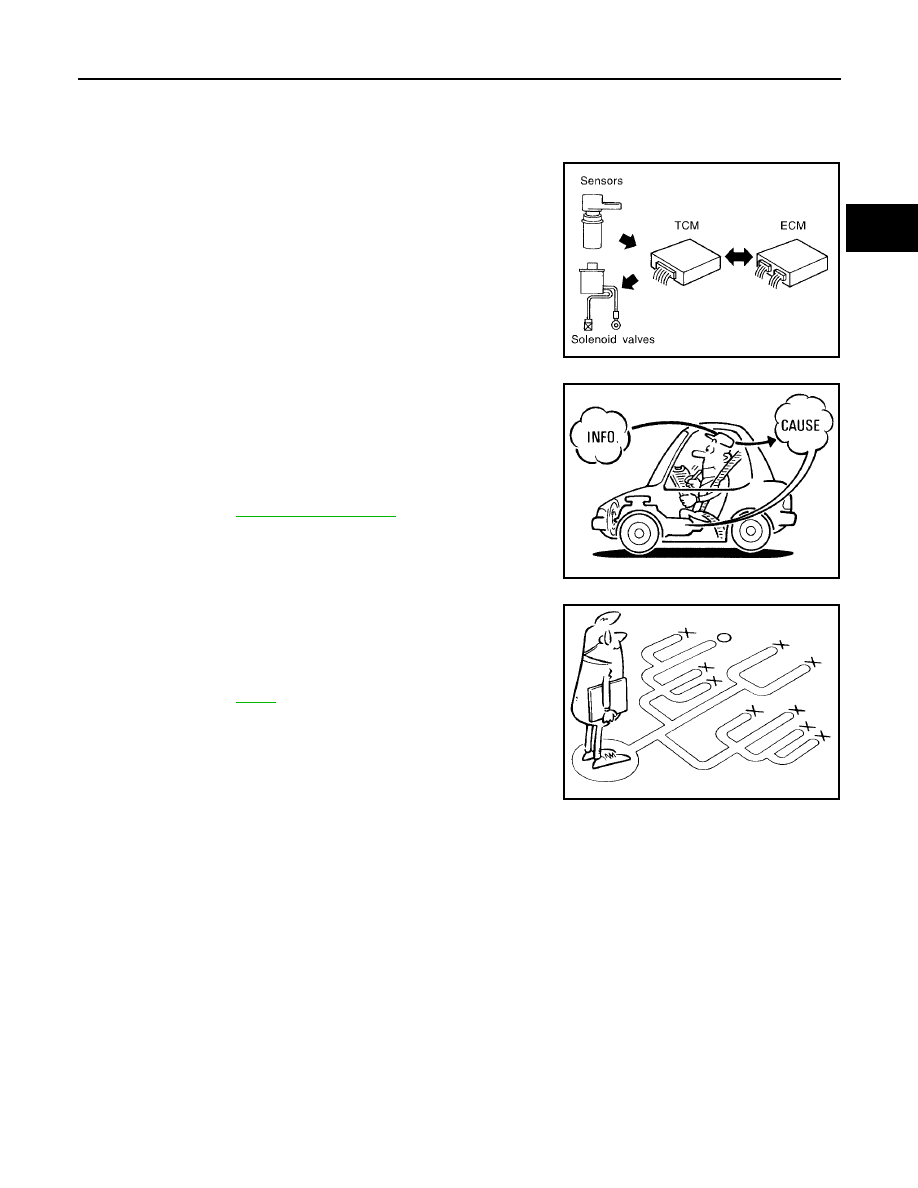
The TCM receives a signal from the vehicle speed sensor, accelerator pedal position sensor (throttle position
sensor) or PNP switch and provides shift control or lock-up control via A/T solenoid valves.
The TCM also communicates with the ECM by means of a signal
sent from sensing elements used with the OBD-related parts of the
A/T system for malfunction-diagnostic purposes. The TCM is capa-
ble of diagnosing malfunctioning parts while the ECM can store mal-
functions in its memory.
Input and output signals must always be correct and stable in the
operation of the A/T system. The A/T system must be in good oper-
ating condition and be free of valve seizure, solenoid valve malfunc-
tion, etc.

It is much more difficult to diagnose a error that occurs intermittently
rather than continuously. Most intermittent errors are caused by poor
electric connections or improper wiring. In this case, careful check-
ing of suspected circuits may help prevent the replacement of good
parts.
A visual check only may not find the cause of the errors. A road test
with CONSULT-II (or GST) or a circuit tester connected should be
performed. Follow the

AT-44, "WORK FLOW"

.

Before undertaking actual checks, take a few minutes to talk with a
customer who approaches with a driveability complaint. The cus-
tomer can supply good information about such errors, especially
intermittent ones. Find out what symptoms are present and under
what conditions they occur. A “Diagnostic Worksheet” as shown on
the example (Refer to

AT-45

) should be used.

Start your diagnosis by looking for “conventional” errors first. This will
help troubleshoot driveability errors on an electronically controlled
engine vehicle.
Also check related Service bulletins.

SAT631IB

SAT632I

SEF234G

AT-44

TROUBLE DIAGNOSIS

2005 Pathfinder

WORK FLOW

A good understanding of the malfunction conditions can make troubleshooting faster and more accurate.
In general, each customer feels differently about a malfunction. It is important to fully understand the symp-
toms or conditions for a customer complaint.
Make good use of the two sheets provided, “Information From Customer” (Refer to

AT-45

) and “Diagnostic

Worksheet” (Refer to

AT-45

), to perform the best troubleshooting possible.

Work Flow Chart

*1.

AT-45

*2.

AT-45

*3.

AT-41

*4.

AT-50

*5.

AT-50

,

AT-51

*6.

AT-53

*7.

AT-84

*8.

AT-37

*9.

AT-100

*10.

AT-177

*11.

AT-183

*12.

AT-219

*13.

AT-61

*14.

AT-38

*15.

AT-100

*16.

EC-49

WCIA0251E

TROUBLE DIAGNOSIS

AT-45

D

E

F

G

H

I

J

K

L

M

A

B

AT

2005 Pathfinder

DIAGNOSTIC WORKSHEET
Information From Customer

KEY POINTS

●

WHAT..... Vehicle & A/T model

●

WHEN..... Date, Frequencies

●

WHERE..... Road conditions

●

HOW..... Operating conditions, Symptoms

Diagnostic Worksheet Chart

Customer name

MR/MS

Model & Year

VIN

Trans. Model

Engine

Mileage

Malfunction Date

Manuf. Date

In Service Date

Frequency

❏

Continuous

❏

Intermittent (times a day)

Symptoms

❏

Vehicle does not move.

(

❏

Any position

❏

Particular position)

❏

No up-shift

(

❏

1st

→

2nd

❏

2nd

→

3rd

❏

3rd

→

4th

❏

4th

→

5th)

❏

No down-shift

(

❏

5th

→

4th

❏

4th

→

3rd

❏

3rd

→

2nd

❏

2nd

→

1st)

❏

Lock-up malfunction

❏

Shift point too high or too low.

❏

Shift shock or slip

(

❏

N

→

D

❏

Lock-up

❏

Any drive position)

❏

Noise or vibration

❏

No kick down

❏

No pattern select

❏

Others

(

)

Malfunction indicator lamp (MIL)

❏

Continuously lit

❏

Not lit

1

❏

Read the item on cautions concerning fail-safe and understand the customer's complaint.

AT-41

2

❏

ATF inspection

AT-50

❏

Leak (Repair leak location.)

❏

State

❏

Amount

3

❏

Stall test and line pressure test

AT-50

,

AT-

51

❏

Stall test

❏

Torque converter one-way clutch

❏

Front brake

❏

High and low reverse clutch

❏

Low coast brake

❏

Forward brake

❏

Reverse brake

❏

Forward one-way clutch

❏

1st one-way clutch

❏

3rd one-way clutch

❏

Engine

❏

Line pressure low

❏

Except for input clutch and direct

clutch, clutches and brakes OK

❏

Line pressure inspection - Suspected part:

AT-46

TROUBLE DIAGNOSIS

2005 Pathfinder

4

❏

Perform all road tests and enter checks in required inspection items.

AT-53

4-1.

Check before engine is started

AT-54

❏

AT-183, "O/D OFF Indicator Lamp Does Not Come On"

❏

Perform self-diagnostics Enter checks for detected items.

AT-87

❏

AT-100, "DTC U1000 CAN COMMUNICATION LINE"

❏

AT-103, "DTC P0615 START SIGNAL CIRCUIT"

❏

AT-107, "DTC P0700 TCM"

❏

AT-108, "DTC P0705 PARK/NEUTRAL POSITION SWITCH"

❏

AT-112, "DTC P0720 VEHICLE SPEED SENSOR A/T (REVOLUTION SENSOR)"

❏

AT-117, "DTC P0725 ENGINE SPEED SIGNAL"

❏

AT-119, "DTC P0740 TORQUE CONVERTER CLUTCH SOLENOID VALVE"

❏

AT-121, "DTC P0744 A/T TCC S/V FUNCTION (LOCK-UP)"

❏

AT-123, "DTC P0745 LINE PRESSURE SOLENOID VALVE"

❏

AT-125, "DTC P1702 TRANSMISSION CONTROL MODULE (RAM)"

❏

AT-126, "DTC P1703 TRANSMISSION CONTROL MODULE (ROM)"

❏

AT-127, "DTC P1705 THROTTLE POSITION SENSOR"

❏

AT-130, "DTC P1710 A/T FLUID TEMPERATURE SENSOR CIRCUIT"

❏

AT-135, "DTC P1716 TURBINE REVOLUTION SENSOR"

❏

AT-137, "DTC P1721 VEHICLE SPEED SENSOR MTR"

❏

AT-139, "DTC P1730 A/T INTERLOCK"

❏

AT-142, "DTC P1731 A/T 1ST ENGINE BRAKING"

❏

AT-144, "DTC P1752 INPUT CLUTCH SOLENOID VALVE"

❏

AT-146, "DTC P1754 INPUT CLUTCH SOLENOID VALVE FUNCTION"

❏

AT-148, "DTC P1757 FRONT BRAKE SOLENOID VALVE"

❏

AT-150, "DTC P1759 FRONT BRAKE SOLENOID VALVE FUNCTION"

❏

AT-152, "DTC P1762 DIRECT CLUTCH SOLENOID VALVE"

❏

AT-154, "DTC P1764 DIRECT CLUTCH SOLENOID VALVE FUNCTION"

❏

AT-156, "DTC P1767 HIGH AND LOW REVERSE CLUTCH SOLENOID VALVE"

❏

AT-158, "DTC P1769 HIGH AND LOW REVERSE CLUTCH SOLENOID VALVE

FUNCTION"

❏

AT-160, "DTC P1772 LOW COAST BRAKE SOLENOID VALVE"

❏

AT-162, "DTC P1774 LOW COAST BRAKE SOLENOID VALVE FUNCTION"

❏

AT-164, "DTC P1841 ATF PRESSURE SWITCH 1"

❏

AT-166, "DTC P1843 ATF PRESSURE SWITCH 3"

❏

AT-168, "DTC P1845 ATF PRESSURE SWITCH 5"

❏

AT-170, "DTC P1846 ATF PRESSURE SWITCH 6"

4-2.

Idle inspection

AT-54

❏

AT-184, "Engine Cannot Be Started In “P” or “N” Position"

❏

AT-185, "In “P” Position, Vehicle Moves When Pushed"

❏

AT-186, "In “N” Position, Vehicle Moves"

❏

AT-187, "Large Shock (“N” to “D” Position)"

❏

AT-189, "Vehicle Does Not Creep Backward In “R” Position"

❏

AT-192, "Vehicle Does Not Creep Forward In “D” Position"

4-3.

Driving tests

AT-55

Part 1

❏

AT-194, "Vehicle Cannot Be Started From D

1

"

❏

AT-196, "A/T Does Not Shift: D

1

→

D

2

"

❏

AT-198, "A/T Does Not Shift: D

2

→

D

3

"

❏

AT-200, "A/T Does Not Shift: D

3

→

D

4

"

❏

AT-202, "A/T Does Not Shift: D

4

→

D

5

"

❏

AT-204, "A/T Does Not Perform Lock-up"

❏

AT-206, "A/T Does Not Hold Lock-up Condition"

❏

AT-208, "Lock-up Is Not Released"

❏

AT-209, "Engine Speed Does Not Return to Idle"

TROUBLE DIAGNOSIS

AT-47

D

E

F

G

H

I

J

K

L

M

A

B

AT

2005 Pathfinder

4

4-3

Part 2

AT-57

❏

AT-194, "Vehicle Cannot Be Started From D

1

"

❏

AT-196, "A/T Does Not Shift: D

1

→

D

2

"

❏

AT-198, "A/T Does Not Shift: D

2

→

D

3

"

❏

AT-200, "A/T Does Not Shift: D

3

→

D

4

"

Part 3

AT-58

❏

AT-211, "A/T Does Not Shift: 5th gear

→

4th gear"

❏

AT-213, "A/T Does Not Shift: 4th gear

→

3rd gear"

❏

AT-215, "A/T Does Not Shift: 3rd gear

→

2nd gear"

❏

AT-217, "A/T Does Not Shift: 2nd gear

→

1st gear"

❏

AT-219, "Vehicle Does Not Decelerate By Engine Brake"

❏

Perform self-diagnostics Enter checks for detected items.

AT-87

❏

AT-100, "DTC U1000 CAN COMMUNICATION LINE"

❏

AT-103, "DTC P0615 START SIGNAL CIRCUIT"

❏

AT-107, "DTC P0700 TCM"

❏

AT-108, "DTC P0705 PARK/NEUTRAL POSITION SWITCH"

❏

AT-112, "DTC P0720 VEHICLE SPEED SENSOR A/T (REVOLUTION SENSOR)"

❏

AT-117, "DTC P0725 ENGINE SPEED SIGNAL"

❏

AT-119, "DTC P0740 TORQUE CONVERTER CLUTCH SOLENOID VALVE"

❏

AT-121, "DTC P0744 A/T TCC S/V FUNCTION (LOCK-UP)"

❏

AT-123, "DTC P0745 LINE PRESSURE SOLENOID VALVE"

❏

AT-125, "DTC P1702 TRANSMISSION CONTROL MODULE (RAM)"

❏

AT-126, "DTC P1703 TRANSMISSION CONTROL MODULE (ROM)"

❏

AT-127, "DTC P1705 THROTTLE POSITION SENSOR"

❏

AT-130, "DTC P1710 A/T FLUID TEMPERATURE SENSOR CIRCUIT"

❏

AT-135, "DTC P1716 TURBINE REVOLUTION SENSOR"

❏

AT-137, "DTC P1721 VEHICLE SPEED SENSOR MTR"

❏

AT-139, "DTC P1730 A/T INTERLOCK"

❏

AT-142, "DTC P1731 A/T 1ST ENGINE BRAKING"

❏

AT-144, "DTC P1752 INPUT CLUTCH SOLENOID VALVE"

❏

AT-146, "DTC P1754 INPUT CLUTCH SOLENOID VALVE FUNCTION"

❏

AT-148, "DTC P1757 FRONT BRAKE SOLENOID VALVE"

❏

AT-150, "DTC P1759 FRONT BRAKE SOLENOID VALVE FUNCTION"

❏

AT-152, "DTC P1762 DIRECT CLUTCH SOLENOID VALVE"

❏

AT-154, "DTC P1764 DIRECT CLUTCH SOLENOID VALVE FUNCTION"

❏

AT-156, "DTC P1767 HIGH AND LOW REVERSE CLUTCH SOLENOID VALVE"

❏

AT-158, "DTC P1769 HIGH AND LOW REVERSE CLUTCH SOLENOID VALVE

FUNCTION"

❏

AT-160, "DTC P1772 LOW COAST BRAKE SOLENOID VALVE"

❏

AT-162, "DTC P1774 LOW COAST BRAKE SOLENOID VALVE FUNCTION"

❏

AT-164, "DTC P1841 ATF PRESSURE SWITCH 1"

❏

AT-166, "DTC P1843 ATF PRESSURE SWITCH 3"

❏

AT-168, "DTC P1845 ATF PRESSURE SWITCH 5"

❏

AT-170, "DTC P1846 ATF PRESSURE SWITCH 6"

5

❏

Inspect each system for items found to be NG in the self-diagnostics and repair or replace the malfunction parts.

6

❏

Perform all road tests and enter the checks again for the required items.

AT-53

7

❏

For any remaining NG items, perform the “diagnostics procedure” and repair or replace the malfunction parts.

See the chart for diagnostics by symptoms. (This chart also contains other symptoms and inspection proce-
dures.)

AT-61

8

❏

Erase the results of the self-diagnostics from the TCM.

AT-38

AT-48

TROUBLE DIAGNOSIS

2005 Pathfinder

A/T Electrical Parts Location

UCS0031U

SCIA6251E

TROUBLE DIAGNOSIS

AT-49

D

E

F

G

H

I

J

K

L

M

A

B

AT

2005 Pathfinder

Circuit Diagram

UCS0031V

BCWA0414E

AT-50

TROUBLE DIAGNOSIS

2005 Pathfinder

Inspections Before Trouble Diagnosis

UCS0031X

A/T FLUID CHECK
Fluid Leakage and Fluid Level Check

●

Inspect for fluid leakage and check the fluid level. Refer to

MA-24, "Changing the Automatic Transmission

Fluid (ATF)"

.

Fluid Condition Check

Inspect the fluid condition.

STALL TEST
Stall Test Procedure

1.

Inspect the amount of engine oil. Replenish the engine oil if necessary.

2.

Drive for about 10 minutes to warm up the vehicle so that the A/
T fluid temperature is 50 to 80

°

C (122 to 176

°

F). Inspect the

amount of ATF. Replenish if necessary.

3.

Securely engage the parking brake so that the tires do not turn.

4.

Engine start, apply foot brake, and place selector lever in “D”
position.

5.

While holding down the foot brake, gradually press down the
accelerator pedal.

6.

Quickly read off the stall speed, then quickly remove your foot
from the accelerator pedal.

CAUTION:

Do not hold down the accelerator pedal for more than 5 sec-
onds during this test.

Fluid condition

Conceivable Cause

Required Operation

Varnished (viscous
varnish state)

Clutch, brake
scorched

Replace the ATF and check the A/T
main unit and the vehicle for mal-
functions (wire harnesses, cooler
pipes, etc.)

Milky white or
cloudy

Water in the fluid

Replace the ATF and check for
places where water is getting in.

Large amount of
metal powder mixed
in

Unusual wear of
sliding parts within
A/T

Replace the ATF and check for
improper operation of the A/T.

SAT638A

SAT647B

SCIA1224E

Stall speed:

2,200 - 2,500 rpm

SAT514G


Content      ..     7      8      9      10     ..