Nissan Pathfinder. Instruction - part 969


  Index      Nissan     Nissan Pathfinder (2014 year) - Service and Repair Instruction


Search            copyright infringement  


Content   ..  967  968  969  970   ..


Nissan Pathfinder. Instruction - part 969


PWO

AC 120V OUTLET MAIN SW

PWO-33

< REMOVAL AND INSTALLATION >

[AC 120 V OUTLET]

C

D

E

F

G

H

I

J

K

L

B

A

O

P

N

AC 120V OUTLET MAIN SW

Removal and Installation

INFOID:0000000009174858

REMOVAL

1. Remove the inverter unit fuse.
2. Remove the instrument lower panel LH. Refer to 

IP-25, "Removal and Installation"

.   

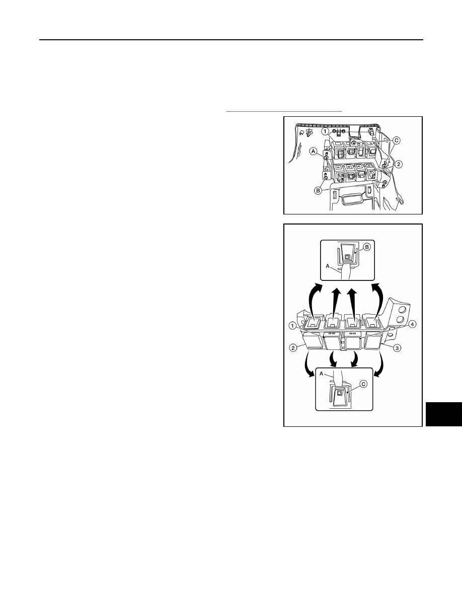
3. Remove three screws (A, B) that retain the lower switch assem-

bly (2).

(1) Upper switch assembly

(C) Upper switch assembly screws

4. Release upper tab (B) and lower tab (C) using a suitable tool

(A), then remove the AC 120V outlet main switch (3) from the

lower switch assembly.

(1) Blank

(2) Blank

(4) Tow mode switch (if equipped)

INSTALLATION

Installation is in the reverse order of removal.

ALMIA0554ZZ

ALMIA0567ZZ

PWO-34

< REMOVAL AND INSTALLATION >

[AC 120 V OUTLET]

AC 120 V OUTLET

AC 120 V OUTLET

Removal and Installation

INFOID:0000000009174859

REMOVAL

1. Remove center console rear finisher. Refer to 

IP-27, "Exploded View"

.

2. Release the pawl from the back of the center console rear finisher to remove the AC 120 V outlet.

INSTALLATION

Installation is in the reverse order of removal.

PWO

SERVICE DATA AND SPECIFICATIONS (SDS)

PWO-35

< SERVICE DATA AND SPECIFICATIONS (SDS) 

[AC 120 V OUTLET]

C

D

E

F

G

H

I

J

K

L

B

A

O

P

N

SERVICE DATA AND SPECIFICATIONS (SDS)

SERVICE DATA AND SPECIFICATIONS (SDS)

AC 120V Power Outlet 

INFOID:0000000009174860

Rated voltage

AC 120 V

Maximum electric capacity

150 W or less (Total)

Maximum current

Up to 30 A (Total)

RAX-1

TRANSMISSION & DRIVELINE

C

E

F

G

H

I

J

K

L

M

SECTION 

RAX

A

B

RAX

N

O

P

CONTENTS

REAR AXLE

PRECAUTION ...............................................

2

PRECAUTIONS ...................................................

2

Precaution for Supplemental Restraint System 
(SRS) "AIR BAG" and "SEAT BELT PRE-TEN-
SIONER" .................................................................
..

2

Precautions for Drive Shaft  .......................................

2

PREPARATION ............................................

3

PREPARATION ...................................................

3

Special Service Tool  .................................................

3

Commercial Service Tool  ..........................................

3

SYMPTOM DIAGNOSIS  ...............................

4

NOISE, VIBRATION AND HARSHNESS 
(NVH) TROUBLESHOOTING  .............................

4

NVH Troubleshooting Chart  ......................................

4

PERIODIC MAINTENANCE ..........................

5

WHEEL HUB  .......................................................

5

On-vehicle Service  ....................................................

5

Inspection ..................................................................

5

REAR DRIVE SHAFT .........................................

6

Inspection .................................................................

6

REMOVAL AND INSTALLATION ................

7

REAR WHEEL HUB ...........................................

7

Exploded View ..........................................................

7

Removal and Installation  ..........................................

7

REAR DRIVE SHAFT .........................................

9

Exploded View ..........................................................

9

Removal and Installation  ..........................................

9

UNIT DISASSEMBLY AND ASSEMBLY  ....

11

REAR DRIVE SHAFT ........................................

11

Disassembly and Assembly .....................................

11

SERVICE DATA AND SPECIFICATIONS 
(SDS) ............................................................

17

SERVICE DATA AND SPECIFICATIONS 
(SDS) .................................................................

17

Wheel Bearing  .........................................................

17

Drive Shaft ...............................................................

17


Content   ..  967  968  969  970   ..