Nissan Pathfinder. Instruction - part 956


  Index      Nissan     Nissan Pathfinder (2014 year) - Service and Repair Instruction


Search            copyright infringement  


Content   ..  954  955  956  957   ..


Nissan Pathfinder. Instruction - part 956


PWC-120

< DTC/CIRCUIT DIAGNOSIS >

[LH & RH FRONT AUTO UP/DOWN]

POWER WINDOW SERIAL LINK

Is the inspection result normal?

YES

>> Power window serial link is OK.

NO

>> GO TO 2.

2.

 CHECK POWER WINDOW SERIAL LINK CIRCUIT

1. Turn ignition switch OFF.

2. Disconnect BCM and main power window and door lock/unlock switch.

3. Check continuity between BCM connector M81 and main power window and door lock/unlock switch con-

nector D25.

4. Check continuity between BCM connector M81 and ground.

Is the inspection result normal?

YES

>> Replace main power window and door lock/unlock switch. Refer to 

PWC-137, "Removal and

Installation"

After that, refer to 

PWC-93, "Work Procedure"

.

NO

>> Repair or replace harness or connectors.

FRONT POWER WINDOW SWITCH
FRONT POWER WINDOW SWITCH : Description

INFOID:0000000009176246

Main power window and door lock/unlock switch, power window and door lock/unlock switch RH and BCM

transmit and receive the signal by power window serial link.

The signal mentioned below is transmitted from BCM to main power window and door lock/unlock switch and

power window and door lock/unlock switch RH

• Keyless power window down signal

The signal mentioned below is transmitted from main power window and door lock/unlock switch to power win-

dow and door lock/unlock switch RH

• Front door window RH operation signal

• Power window control by key cylinder switch signal

• Retained power operation signal 

• Power window lock switch signal

FRONT POWER WINDOW SWITCH : Component Function Check

INFOID:0000000009176247

1.

 CHECK POWER WINDOW AND DOOR LOCK/UNLOCK SWITCH RH OUTPUT SIGNAL

Check (“CDL LOCK SW ”, “CDL UNLOCK SW”) in “DATA MONITOR” mode for “POWER DOOR LOCK SYS-

TEM” with CONSULT. Refer to 

BCS-15, "DOOR LOCK : CONSULT Function (BCM - DOOR LOCK)"
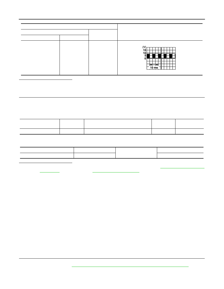
.

Terminal

Signal

(Reference value)

(+)

(–)

BCM connector

Terminal 

M81

54

Ground

PIIA1297E

BCM connector

Terminal

Main power window and door lock/unlock 

switch connector

Terminal

Continuity

M81

54

D25

11

Yes

BCM connector

Terminal

Ground

Continuity 

M81

54

No

POWER WINDOW SERIAL LINK

PWC-121

< DTC/CIRCUIT DIAGNOSIS >

[LH & RH FRONT AUTO UP/DOWN]

C

D

E

F

G

H

I

J

L

M

A

B

PWC

N

O

P

Is the inspection result normal?

YES

>> Power window serial link is OK.

NO

>> Refer to 

PWC-121, "FRONT POWER WINDOW SWITCH : Diagnosis Procedure"

.

FRONT POWER WINDOW SWITCH : Diagnosis Procedure

INFOID:0000000009176248

Regarding Wiring Diagram information, refer to 

PWC-80, "Wiring Diagram - With Left & Right Front Auto Up/

Down"

.

Power Window Serial Link Check

1.

 CHECK POWER WINDOW AND DOOR LOCK/UNLOCK SWITCH RH

1. Remove Intelligent Key, and close the front door LH and RH.

2. Check signal between BCM connector and ground with oscilloscope when door lock and unlock switch

(LH and RH) is turned to “LOCK” or “UNLOCK”.

3. Check that signals which are shown in the figure below can be detected during 10 second just after door

lock and unlock switch (LH and RH) is turned to “LOCK” or “UNLOCK”.

Is the inspection result normal?

YES

>> Power window serial link is OK.

NO

>> GO TO 2.

2.

 CHECK POWER WINDOW SERIAL LINK CIRCUIT

1. Turn ignition switch OFF.

2. Disconnect BCM.

3. Check continuity between BCM connector M81 and power window and door lock/unlock switch RH con-

nector D129.

4. Check continuity between BCM connector M81 and ground.

Is the inspection result normal?

Monitor item

Condition

CDL LOCK SW 

LOCK

: ON

UNLOCK

: OFF

CDL UNLOCK SW 

LOCK

: OFF

UNLOCK

: ON

Terminal

Signal

(Reference value)

(+)

(–)

BCM connector

Terminal 

M81

54

Ground

PIIA1297E

BCM connector

Terminal

Power window and door lock/unlock switch RH connector

Terminal

Continuity

M81

54

D129

3

Yes

BCM connector

Terminal

Ground

Continuity 

M81

54

No

PWC-122

< DTC/CIRCUIT DIAGNOSIS >

[LH & RH FRONT AUTO UP/DOWN]

POWER WINDOW SERIAL LINK

YES

>> Replace main power window and door lock/unlock switch. Refer to 

PWC-137, "Removal and

Installation"

After that, refer to 

PWC-93, "Work Procedure"

.

NO

>> Repair or replace the harness or connectors.

POWER WINDOWS DO NOT OPERATE WITH POWER WINDOW MAIN SWITCH

PWC-123

< SYMPTOM DIAGNOSIS >

[LH & RH FRONT AUTO UP/DOWN]

C

D

E

F

G

H

I

J

L

M

A

B

PWC

N

O

P

SYMPTOM DIAGNOSIS

POWER WINDOWS DO NOT OPERATE WITH POWER WINDOW MAIN
SWITCH

Diagnosis Procedure

INFOID:0000000009176249

1.

 CHECK BCM POWER SUPPLY AND GROUND CIRCUIT

Check BCM power supply and ground circuit.

Refer to 

BCS-74, "Diagnosis Procedure"

.

Is the inspection result normal?

YES

>> GO TO 2.

NO

>> Repair or replace the malfunctioning parts.

2.

 CHECK MAIN POWER WINDOW AND DOOR LOCK/UNLOCK SWITCH

Check main power window and door lock/unlock switch.

Refer to 

PWC-98, "POWER WINDOW MAIN SWITCH : Component Inspection"

.

Is the inspection result normal?

YES

>> GO TO 3.

NO

>> Repair or replace the malfunctioning parts.

3.

 CHECK MAIN POWER WINDOW AND DOOR LOCK/UNLOCK SWITCH POWER SUPPLY AND

GROUND CIRCUIT

Check power window switch main power supply and ground circuit.

Refer to 

PWC-96, "POWER WINDOW MAIN SWITCH : Component Function Check"

.

Is the inspection result normal?

YES

>> GO TO 4.

NO

>> Repair or replace the malfunctioning parts.

4.

 CHECK MAIN POWER WINDOW AND DOOR LOCK/UNLOCK SWITCH SERIAL CIRCUIT

Check main power window and door lock/unlock switch serial circuit.

Refer to 

PWC-119, "POWER WINDOW MAIN SWITCH : Component Function Check"

.

Is the inspection result normal?

YES

>> Check intermittent incident. Refer to 

GI-49, "Intermittent Incident"

.

NO

>> Repair or replace the malfunctioning parts.


Content   ..  954  955  956  957   ..