Nissan Pathfinder. Instruction - part 793


  Index      Nissan     Nissan Pathfinder (2014 year) - Service and Repair Instruction


Search            copyright infringement  


Content   ..  791  792  793  794   ..


Nissan Pathfinder. Instruction - part 793


LAN

MAIN LINE BETWEEN IPDM-E AND ABS CIRCUIT

LAN-125

< DTC/CIRCUIT DIAGNOSIS >

[CAN SYSTEM (TYPE 2)]

C

D

E

F

G

H

I

J

K

L

B

A

O

P

N

DTC/CIRCUIT DIAGNOSIS

MAIN LINE BETWEEN IPDM-E AND ABS CIRCUIT

Diagnosis Procedure

INFOID:0000000009175018

1.

CHECK HARNESS CONTINUITY (OPEN CIRCUIT)

1. Turn the ignition switch OFF.

2. Disconnect the battery cable from the negative terminal.

3. Disconnect the following harness connectors.

-

ECM

-

IPDM E/R

-

ABS actuator and electric unit (control unit)

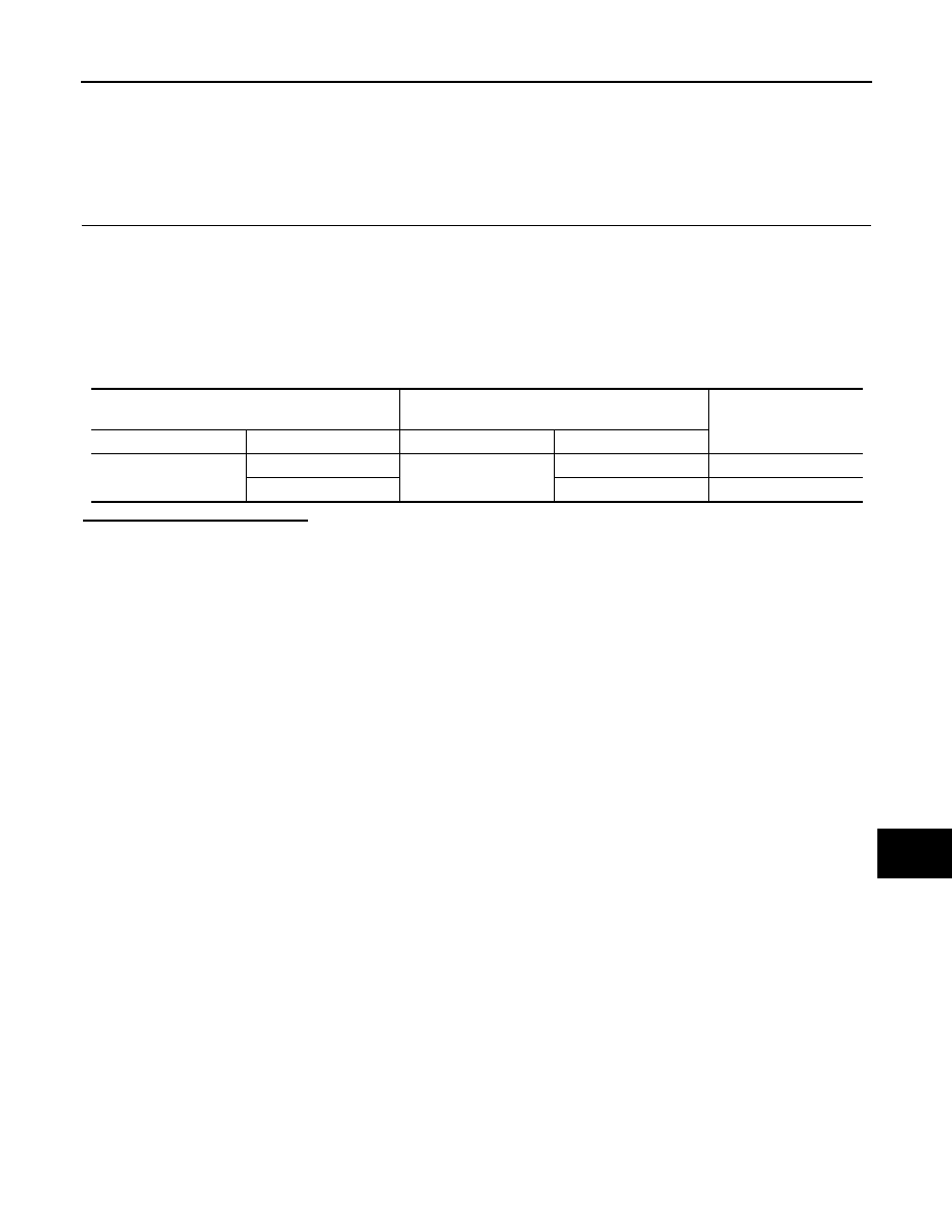
4. Check the continuity between the IPDM E/R harness connector and the ABS actuator and electric unit

(control unit) harness connector.

Is the inspection result normal?

YES (Present error)>>Check CAN system type decision again.

YES (Past error)>>Error was detected in the main line between the IPDM E/R and the ABS actuator and

electric unit (control unit). 

NO

>> Repair the main line between the IPDM E/R and the ABS actuator and electric unit (control unit).

IPDM E/R harness connector

ABS actuator and electric unit (control unit) 

harness connector

Continuity

Connector No.

Terminal No.

Connector No.

Terminal No.

E119

29

E125

25

Existed

28

15

Existed

LAN-126

< DTC/CIRCUIT DIAGNOSIS >

[CAN SYSTEM (TYPE 2)]

MAIN LINE BETWEEN ABS AND DLC CIRCUIT

MAIN LINE BETWEEN ABS AND DLC CIRCUIT

Diagnosis Procedure

INFOID:0000000009175019

1.

CHECK CONNECTOR

1. Turn the ignition switch OFF.

2. Disconnect the battery cable from the negative terminal.

3. Check the following terminals and connectors for damage, bend and loose connection (connector side

and harness side).

-

Harness connector E152

-

Harness connector M31

Is the inspection result normal?

YES

>> GO TO 2.

NO

>> Repair the terminal and connector.

2.

CHECK HARNESS CONTINUITY (OPEN CIRCUIT)

1. Disconnect the following harness connectors.

-

ABS actuator and electric unit (control unit)

-

Harness connectors E152 and M31.

2. Check the continuity between the ABS actuator and electric unit (control unit) harness connector and the

harness connector.

Is the inspection result normal?

YES

>> GO TO 3.

NO

>> Repair the main line between the ABS actuator and electric unit (control unit) and the harness

connector E152.

3.

CHECK HARNESS CONTINUITY (OPEN CIRCUIT)

Check the continuity between the harness connector and the data link connector.

Is the inspection result normal?

YES (Present error)>>Check CAN system type decision again.

YES (Past error)>>Error was detected in the main line between the ABS actuator and electric unit (control

unit) and the data link connector. 

NO

>> Repair the main line between the harness connector M31 and the data link connector.

ABS actuator and electric unit (control unit) harness 

connector

Harness connector

Continuity

Connector No.

Terminal No.

Connector No.

Terminal No.

E125

25

E152

36G

Existed

15

35G

Existed

Harness connector

Data link connector

Continuity

Connector No.

Terminal No.

Connector No.

Terminal No.

M31

36G

M22

6

Existed

35G

14

Existed

LAN

ECM BRANCH LINE CIRCUIT

LAN-127

< DTC/CIRCUIT DIAGNOSIS >

[CAN SYSTEM (TYPE 2)]

C

D

E

F

G

H

I

J

K

L

B

A

O

P

N

ECM BRANCH LINE CIRCUIT

Diagnosis Procedure

INFOID:0000000009175020

1.

CHECK CONNECTOR

1. Turn the ignition switch OFF.

2. Disconnect the battery cable from the negative terminal.

3. Check the terminals and connectors of the ECM for damage, bend and loose connection (unit side and

connector side).

Is the inspection result normal?

YES

>> GO TO 2.

NO

>> Repair the terminal and connector.

2.

CHECK HARNESS FOR OPEN CIRCUIT

1. Disconnect the connector of ECM.

2. Check the resistance between the ECM harness connector terminals.

Is the measurement value within the specification?

YES

>> GO TO 3.

NO

>> Repair the ECM branch line.

3.

CHECK POWER SUPPLY AND GROUND CIRCUIT

Check the power supply and the ground circuit of the ECM. Refer to 

EC-173, "Diagnosis Procedure"

.

Is the inspection result normal?

YES (Present error)>>Replace the ECM. Refer to 

EC-466, "Removal and Installation"

.

YES (Past error)>>Error was detected in the ECM branch line.

NO

>> Repair the power supply and the ground circuit.

ECM harness connector

Resistance (

Ω)

Connector No.

Terminal No.

E16

114

113

Approx. 108 – 132

LAN-128

< DTC/CIRCUIT DIAGNOSIS >

[CAN SYSTEM (TYPE 2)]

IPDM-E BRANCH LINE CIRCUIT

IPDM-E BRANCH LINE CIRCUIT

Diagnosis Procedure

INFOID:0000000009175021

1.

CHECK CONNECTOR

1. Turn the ignition switch OFF.

2. Disconnect the battery cable from the negative terminal.

3. Check the terminals and connectors of the IPDM E/R for damage, bend and loose connection (unit side

and connector side).

Is the inspection result normal?

YES

>> GO TO 2.

NO

>> Repair the terminal and connector.

2.

CHECK HARNESS FOR OPEN CIRCUIT

1. Disconnect the connector of IPDM E/R.

2. Check the resistance between the IPDM E/R harness connector terminals.

Is the measurement value within the specification?

YES

>> GO TO 3.

NO

>> Repair the IPDM E/R branch line.

3.

CHECK POWER SUPPLY AND GROUND CIRCUIT

Check the power supply and the ground circuit of the IPDM E/R. Refer to 

PCS-31, "Diagnosis Procedure"

.

Is the inspection result normal?

YES (Present error)>>Replace the IPDM E/R. Refer to 

PCS-32, "Removal and Installation"

.

YES (Past error)>>Error was detected in the IPDM E/R branch line.

NO

>> Repair the power supply and the ground circuit.

IPDM E/R harness connector

Resistance (

Ω)

Connector No.

Terminal No.

E119

29

28

Approx. 54 – 66


Content   ..  791  792  793  794   ..