Nissan Pathfinder. Instruction - part 674


  Index      Nissan     Nissan Pathfinder (2014 year) - Service and Repair Instruction


Search            copyright infringement  


Content   ..  672  673  674  675   ..


Nissan Pathfinder. Instruction - part 674


PRECAUTIONS

HA-7

< PRECAUTION >

C

D

E

F

G

H

J

K

L

M

A

B

HA

N

O

P

• Read and follow all manufacturer’s operating instructions and precautions prior to performing the

work for the purpose of safety and customer’s satisfaction.

• A compressor shaft seal should not necessarily be repaired because of dye seepage. The compres-

sor shaft seal should only be repaired after confirming the leakage with an electronic leak detector

(SST: J-41995).

• Always remove any remaining dye from the leakage area after repairs are completed to avoid a mis-

diagnosis during a future service.

• Do not allow dye to come into contact with painted body panels or interior components. Clean imme-

diately with the approved dye cleaner if dye is spilled. Fluorescent dye left on a surface for an

extended period of time cannot be removed.

• Do not spray the fluorescent dye cleaning agent on hot surfaces (engine exhaust manifold, etc.).

• Do not use more than one refrigerant dye bottle [1/4 ounce (7.4 cc)] per A/C system.

• Leak detection dyes for HFC-134a (R-134a) and CFC-12 (R-12) A/C systems are different. Do not use

HFC-134a (R-134a) leak detection dye in CFC-12 (R-12) A/C system or CFC-12 (R-12) leak detection

dye in HFC-134a (R-134a) A/C system or A/C system damage may result.

• The fluorescent properties of the dye remains for three or more years unless a compressor malfunc-

tion occurs.

NOTE:

Identification

• Vehicles with factory installed fluorescent dye have a green label.

• Vehicles without factory installed fluorescent dye have a blue label.

Service Equipment

INFOID:0000000009723959

RECOVERY/RECYCLING RECHARGING EQUIPMENT

Be certain to follow the manufacturer’s instructions for machine operation and machine maintenance. Do not

introduce any refrigerant other than that specified into the machine.

ELECTRONIC LEAK DETECTOR

Be certain to follow the manufacturer’s instructions for detector operation and maintenance.
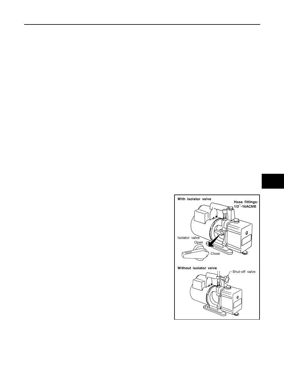
VACUUM PUMP

The oil contained inside the vacuum pump is not compatible with the

specified oil for HFC-134a (R-134a) A/C systems. The vent side of

the vacuum pump is exposed to atmospheric pressure, so the vac-

uum pump oil may migrate out of the pump into the service hose.

This is possible when the pump is switched OFF after evacuation

(vacuuming) and hose is connected to it.

To prevent this migration, use a instruction valve placed near the hose-

to-pump connection, as per the following.

• Vacuum pumps usually have a instruction isolator valve as part of the

pump. Close this valve to isolate the service hose from the pump.

• Use a hose equipped with a instruction shut-off valve near the pump

end for pumps without an isolator. Close the valve to isolate the

hose from the pump.

• Disconnect the hose from the pump if the hose has an automatic

shut-off valve. As long as the hose is connected, the valve is open

and oil may migrate.

Some one-way valves open when vacuum is applied and close

under no vacuum condition. Such valves may restrict the pump’s

ability to pull a deep vacuum and are not recommended.

MANIFOLD GAUGE SET

RHA270DA

HA-8

< PRECAUTION >

PRECAUTIONS

Be certain that the gauge face indicates HFC-134a or R-134a. Be

sure the gauge set has 1/2

″-16 ACME threaded connections for ser-

vice hoses. Confirm the set has been used only with refrigerant

HFC-134a (R-134a) and specified oils.

SERVICE HOSES

Be certain that the service hoses display the markings described

(colored hose with black stripe). All hoses must include positive shut-

off devices (either instruction or automatic) near the end of the hoses

opposite to the manifold gauge.

SERVICE COUPLERS

Do not attempt to connect HFC-134a (R-134a) service couplers to

the CFC-12 (R-12) A/C system. The HFC-134a (R-134a) couplers

do not properly connect to the CFC-12 (R-12) system. However, if an

improper connection is attempted, discharging and contamination

may occur.

REFRIGERANT WEIGHT SCALE

Verify that no refrigerant other than HFC-134a (R-134a) and speci-

fied oils have been used with the scale. The hose fitting must be 1/

2

″-16 ACME if the scale controls refrigerant flow electronically.

CHARGING CYLINDER

Using a charging cylinder is not recommended. Refrigerant may be vented into air from cylinder’s top valve

when filling the cylinder with refrigerant. Also, the accuracy of the cylinder is generally less than that of an

electronic scale or of quality recycle/recharge equipment.

SHA533D

RHA272D

Shut-off valve rotation

A/C service valve

Clockwise

Open

Counterclockwise

Close

RHA273D

RHA274D

PREPARATION

HA-9

< PREPARATION >

C

D

E

F

G

H

J

K

L

M

A

B

HA

N

O

P

PREPARATION

PREPARATION

Special Service Tool

INFOID:0000000009176717

The actual shapes of Kent-Moore tools may differ from those of special service tools illustrated here.

Commercial Service Tool

INFOID:0000000009176718

Tool number
(Kent-Moore No.)
Tool name

Description

(J-41425-NIS)
Aluminum tube repair kit

Repairing leaks in A/C tubes

(J-38873-A)
Drive plate installer

Installing pulley

ALIIA0390ZZ

WJIA0367E

(Kent-Moore No.)
Tool name

Description

(J-41810-NI)
Refrigerant identifier equipment (R-
134a)

For checking refrigerant purity and 
system contamination

( — )
Power tool

Loosening nuts, screws and bolts

(J-48710)
NISSAN ACR2009 RRR Unit

Refrigerant recovery, recycling and re-
charging

RJIA0197E

PIIB1407E

WJIA0293E

HA-10

< PREPARATION >

PREPARATION

(J-41995)
Electronic refrigerant leak detector

Power supply:
• DC 12V (battery terminal)

(J-43926)
Refrigerant dye leak detection kit
Kit includes:
(J-42220)
UV lamp and UV safety goggles
(J-41459)
Refrigerant dye injector
(J-41447)
Fluorescent leak detection dye 
(box of 24, 1/4 ounce bottles)
(J-43872)
Refrigerant dye cleaner

Power supply:
• DC 12V (battery terminal)

(J-39183-C)
Manifold gauge set (with hoses and 
couplers)

Identification:
• The gauge face indicates R-134a.

Fitting size-Thread size

• 1/2”-16 ACME

Service hoses:
• High side hose

(J-39500-72B)

• Low side hose

(J-39500-72R)

• Utility hose

(J-39500-72Y)

Hose color:
• Low side hose: Blue with black stripe
• High side hose: Red with black 

stripe

• Utility hose: Yellow with black stripe 

or green with black stripe
Hose fitting to gauge:

• 1/2”-16 ACME

Service couplers
• High side coupler

(J-39500-20A)

• Low side coupler

(J-39500-24A)

Hose fitting to service hose:
• M14 x 1.5 fitting is optional or per-

manently attached.

(Kent-Moore No.)
Tool name

Description

AHA281A

ZHA200H

RJIA0196E

S-NT201

S-NT202


Content   ..  672  673  674  675   ..