Nissan Pathfinder. Instruction - part 638
FL-8
< REMOVAL AND INSTALLATION >
FUEL LEVEL SENSOR UNIT, FUEL FILTER AND FUEL PUMP ASSEMBLY
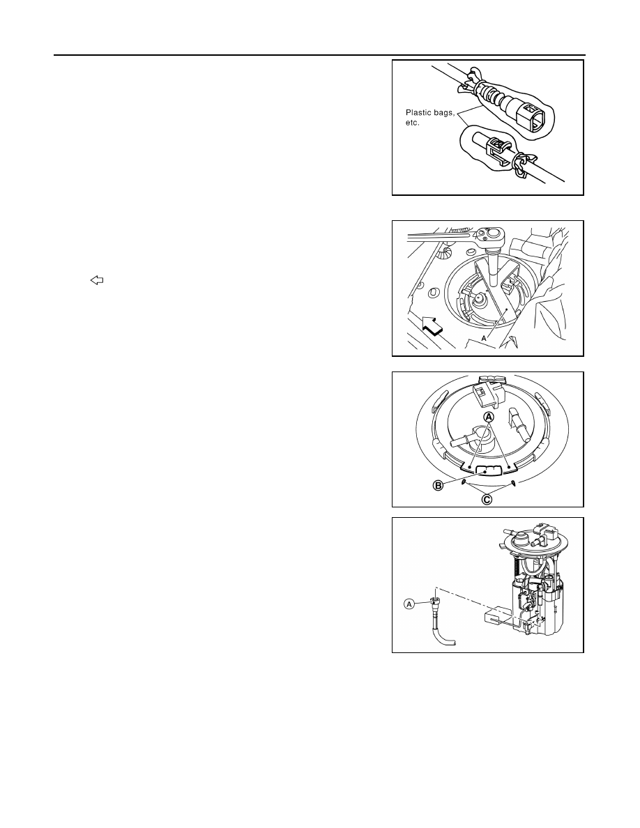
• To keep the connecting portion clean and to avoid dam-
age and foreign materials, cover them completely with
plastic bags or something similar.
11. Remove the lock ring from the fuel level sensor, fuel filter, and fuel pump assembly.
• Remove the lock ring using Tool (A).
• Prior to removal, observe the alignment between the fuel level
sensor, fuel filter, and fuel pump assembly tabs (A) and the
matching marks (C) on the fuel tank as shown. This alignment
is necessary for proper installation.
12. Raise the fuel level sensor, fuel filter, and fuel pump assembly
high enough to gain access and disconnect the transfer tube
connector (A).
CAUTION:
Do not pull on the transfer tube or damage to the fuel tank
can occur.
13. Remove the fuel level sensor, fuel filter, and fuel pump assembly
and O-ring. Discard the O-ring.
CAUTION:
Do not bend the float arm during removal.
INSPECTION AFTER REMOVAL
Inspect the fuel level sensor, fuel filter, and fuel pump for any defects and foreign materials. Replace as neces-
sary.
INSTALLATION
1. Install the fuel level sensor, fuel filter, and fuel pump assembly with the following procedure.
CAUTION:
• It is important that the fuel level sensor, fuel filter, and fuel pump assembly be installed carefully,
according to the method in this step to prevent the transfer hose from being pinched under the
fuel pump and to ensure it is routed correctly inside the tank.
• Do not reuse O-ring.
PBIC0163E
Tool number
: ( — ) J-45747
: Front
ALBIA0784ZZ
(B)
: Retainer mounting pawl
JPBIA4665ZZ
ALBIA0785ZZ