Nissan Pathfinder. Instruction - part 572
CYLINDER BLOCK
EM-127
< UNIT DISASSEMBLY AND ASSEMBLY >
C
D
E
F
G
H
I
J
K
L
M
A
EM
N
P
O
6. Install main bearing caps, and tighten to the specified torque. Otherwise, cylinder bores may be distorted
after boring.
7. Cut cylinder bores.
• When any cylinder needs boring, all other cylinders must also be bored.
• Do not cut too much out of cylinder bore at a time. Cut only 0.05 mm (0.0020 in) or so in diameter
at a time.
8. Hone cylinders to obtain specified piston-to-bore clearance.
9. Measure finished cylinder bore for out-of-round and taper.
• Measurement should be done after cylinder bore cools down.
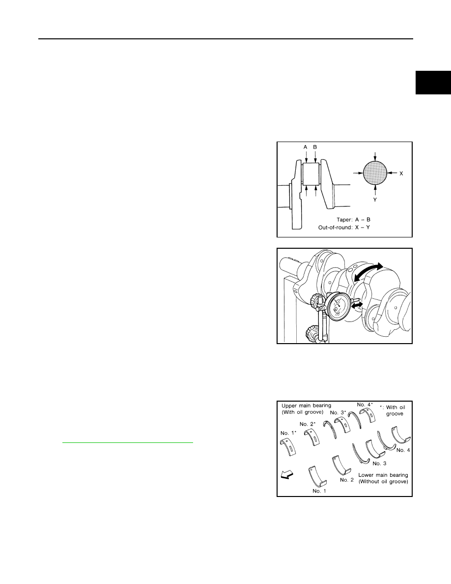
CRANKSHAFT
1. Check the crankshaft main and pin journals for scoring, wear, or
cracks.
2. Measure the journals for taper and out-of-round.
3. Measure crankshaft runout.
a. Place a V-block on a precise flat table to support the journals on
the both ends of the crankshaft.
b. Place a dial gauge straight up on the No. 3 journal.
c. While rotating the crankshaft, read the movement of the pointer
on the dial gauge.
BEARING CLEARANCE
• Use either of the following two methods, however method (A) gives more reliable results and so is the pre-
ferred method.
Method A (Using Bore Gauge and Micrometer)
Main Bearing
1. Set the main bearings in their proper positions on the cylinder
block and the main bearing cap.
2. Install the main bearing caps and bearing beam to the cylinder
block. Tighten all bolts in the numerical order as specified. Refer
EM-112, "Disassembly and Assembly"
.
Standard
Out-of-round (X - Y) : 0.002 mm (0.0001 in)
Taper (A - B)
: 0.002 mm (0.0001 in)
SEM316A
Runout limit (total indicator
reading)
: 0.10 mm (0.0039 in)
SEM346D
SEM175F