Nissan Pathfinder. Instruction - part 555


  Index      Nissan     Nissan Pathfinder (2014 year) - Service and Repair Instruction


Search            copyright infringement  


Content   ..  553  554  555  556   ..


Nissan Pathfinder. Instruction - part 555


FRONT TIMING CHAIN CASE

EM-59

< REMOVAL AND INSTALLATION >

C

D

E

F

G

H

I

J

K

L

M

A

EM

N

P

O

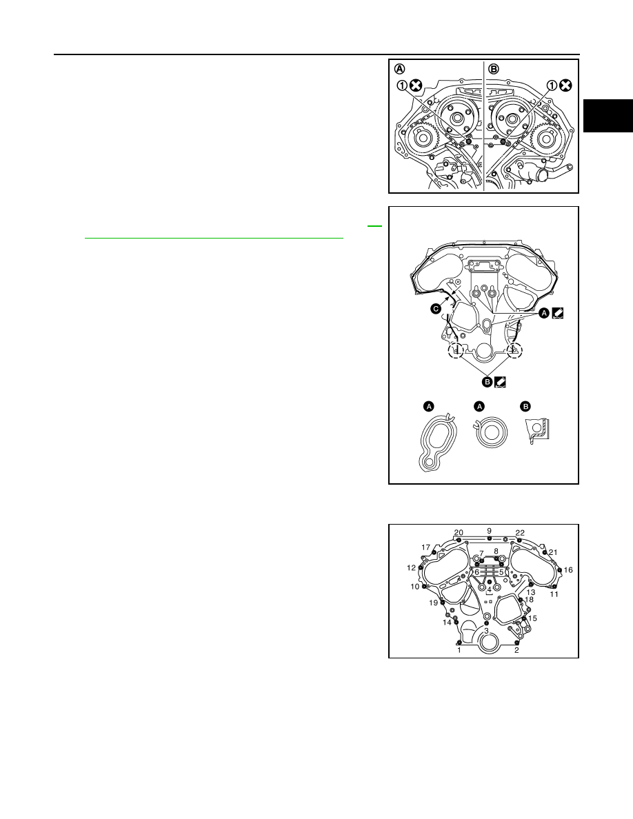
3. Install new O-rings (1) on rear timing chain case.

CAUTION:

Do not reuse O-rings.

4. Apply liquid gasket to front timing chain case as shown.

• Use Genuine Silicone RTV Sealant or equivalent. Refer to 

GI-

22, "Recommended Chemical Products and Sealants"

.

• Before installation, wipe off the protruding liquid gasket.

• (C): 2.6 - 3.6 mm (0.102 - 0.142 in) diameter.

CAUTION:

• Installation should be done within 5 minutes after apply-

ing liquid gasket.

• Do not fill the engine with engine oil for at least 30 min-

utes after the components are installed to allow the liquid

gasket to cure.

5. Install the front timing chain case by aligning the dowel pin on the rear timing chain case with the dowel

pin hole in front timing chain case.

6. Loosely install the front timing chain case bolts.

7. Tighten the front timing chain case bolts in the order shown.

• Retighten the front timing chain case bolts in the order shown.

(A)

: Bank 1 (RH)

(B)

: Bank 2 (LH)

JPBIA1111ZZ

ALBIA0252ZZ

Bolt position Bolt diameter
1, 2

: 8 mm (0.31 in)

3 – 22

: 6 mm (0.24 in)

Bolt position Tightening specification
1, 2

: 28.4 N·m (2.9 kg-m, 21 ft-lb)

3 – 22

: 12.7 N·m (1.3 kg-m, 9 ft-lb)

JPBIA1640ZZ

EM-60

< REMOVAL AND INSTALLATION >

FRONT TIMING CHAIN CASE

8. Install upper oil pan bolts (1) and (2) as shown. Refer to 

EM-37,

"Removal and Installation (Upper Oil Pan)"

.

9. Install intake valve timing control solenoid valve cover (RH) and intake valve timing control solenoid valve

cover (LH).

a. Install new seal rings in shaft grooves.

CAUTION:

• When replacing seal rings, replace all rings with new ones on both intake valve timing control

solenoid valve cover (RH) and intake valve timing control solenoid valve cover (LH).

• Do not reuse O-rings.

b. Install intake valve timing control solenoid valve cover (RH) and intake valve timing control solenoid valve

cover (LH) with new gaskets to front timing chain case.

CAUTION:

Ensure the seal ring remains in the shaft groove.

c.

Being careful not to move seal ring from the installation groove, align the dowel pins on the front timing

chain case with the holes to install intake valve timing control solenoid valve covers.

d. Tighten bolts in the numerical order as shown.

10. Install the water pump. Refer to 

CO-19, "Removal and Installation"

.

11. Install crankshaft pulley and tighten the bolt in two steps.

• Lubricate thread and seat surface of the bolt with new engine oil.

• For the second step, angle tighten using Tool.

CAUTION:

• Do not damage the front oil seal when inserting crankshaft pulley. 

• Use only brass or plastic hammer if tapping on the crankshaft pulley.

• Do not hammer on pulley grooves. 

WBIA0259E

Intake valve timing control 
solenoid valve cover bolts

: 11.3 N·m (1.2 kg-m, 8 ft-lb)

(A)

: Bank 1 (RH)

(B)

: Bank 2 (LH)

(C)

: Dowel pin hole

AWBIA1234GB

FRONT TIMING CHAIN CASE

EM-61

< REMOVAL AND INSTALLATION >

C

D

E

F

G

H

I

J

K

L

M

A

EM

N

P

O

12. Remove the Tool to unlock the driveplate.

CAUTION:

Do not damage the ring gear teeth or the signal plate teeth behind the ring gear when removing

the Tool.

13. Rotate crankshaft pulley in normal direction (clockwise when viewed from front) to confirm it turns

smoothly.

14. Installation of the remaining components is in the reverse order of removal.

INSPECTION AFTER INSTALLATION

• Before starting engine, check oil/fluid levels including engine coolant and engine oil. If there is less than

required quantity, fill to the specified level. Refer to 

MA-15, "FOR USA AND CANADA : Fluids and Lubri-

cants"

 (United States and Canada) or 

MA-16, "FOR MEXICO : Fluids and Lubricants"

 (Mexico).

• Use procedure below to check for fuel leaks.

• Turn ignition switch ON (with engine stopped). With fuel pressure applied to fuel piping, check for fuel leaks

at connection points.

• Start engine. With engine speed increased, check again for fuel leaks at connection points.

• Run engine to check for unusual noise and vibration.

NOTE:

If hydraulic pressure inside timing chain tensioner drops after removal and installation, slack in the guide

may generate a pounding noise during and just after engine start. However, this is normal. Noise will stop

after hydraulic pressure rises.

• Warm up engine thoroughly to make sure there are no leaks of fuel, exhaust gas, or any oils/fluids including

engine oil and engine coolant.

• Bleed air from passages in lines and hoses, such as in cooling system.

• After cooling down engine, again check oil/fluid levels including engine oil and engine coolant. Refill to spec-

ified level, if necessary.

• Summary of the inspection items:

*Power steering fluid, brake fluid, etc.

Step 1

: 44.1 N·m (4.5 kg-m, 33 ft-lb)

Step 2 

: 90

°(+0°/-6°) clockwise

Tool number

: KV10112100 (BT-8653-A)

Tool number

: — (J-50288) 

Item

Before starting engine

Engine running

After engine stopped

Engine coolant

Level

Leaks

Level

Engine oil

Level

Leaks

Level

Transaxle fluid 

CVT Models

Leaks

Level/Leaks

Leaks

Level/Leaks

Leaks

Level/Leaks

Other oils and fluids*

Level

Leaks

Level

Fuel

Leaks

Leaks

Leaks

Exhaust gas

Leaks

EM-62

< REMOVAL AND INSTALLATION >

TIMING CHAIN

TIMING CHAIN

Exploded View

INFOID:0000000009177924

Removal and Installation

INFOID:0000000009177925

CAUTION:

• After removing timing chains, do not turn the crankshaft and camshaft separately or the valves will

strike the pistons.

• When installing camshafts, chain tensioners, oil seals, or other sliding parts, lubricate contacting

surfaces with new engine oil.

• Apply new engine oil to bolt threads and seat surfaces when installing camshaft sprockets, camshaft

brackets, and crankshaft pulley.

REMOVAL

1. Remove front timing chain case. Refer to 

EM-54, "Removal and Installation"

.

2. Remove the intake manifold collector. Refer to 

EM-26, "Removal and Installation"

.

3. Remove the spark plugs. Refer to 

EM-16, "Removal and Installation"

.

4. Place paint marks on the timing chain and sprockets to indicate the correct position of the components for

installation.

5. Disconnect the camshaft position sensor harness connectors. 
6. Remove the timing chain tensioner (primary).

1.

Timing chain tensioner (secondary) (LH) 2.

Internal chain guide

3.

Timing chain tensioner (secondary) (RH)

4.

Camshaft sprocket RH (EXH)

5.

Timing chain (secondary)

6.

Timing chain (primary)

7.

Camshaft sprocket RH (INT)

8.

Slack guide

9.

Timing chain tensioner (primary) 

10. Crankshaft sprocket

11. Camshaft sprocket LH (INT) 12. Timing chain (secondary)

13. Camshaft sprocket LH (EXH)

14. Tension guide

AWBIA1637ZZ


Content   ..  553  554  555  556   ..