Nissan Pathfinder. Instruction - part 518


  Index      Nissan     Nissan Pathfinder (2014 year) - Service and Repair Instruction


Search            copyright infringement  


Content   ..  516  517  518  519   ..


Nissan Pathfinder. Instruction - part 518


EC-378

< DTC/CIRCUIT DIAGNOSIS >

[VQ35DE]

P1564 ASCD STEERING SWITCH

Component Inspection

INFOID:0000000009178297

1.

CHECK ASCD STEERING SWITCH

1. Turn ignition switch OFF.

2. Disconnect combination switch (spiral cable) harness connector.

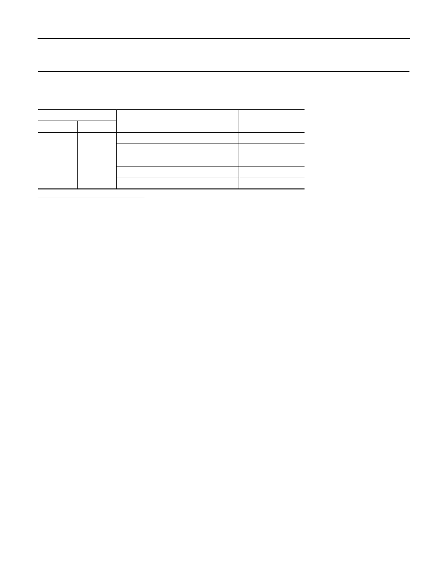
3. Check resistance between combination switch harness connector terminals as per the following.

Is the inspection result normal?

YES

>> INSPECTION END

NO

>> Replace ASCD steering switch. Refer to 

ST-44, "Removal and Installation"

.

Combination switch

Condition

Resistance (

Ω)

Connector

Terminals

M149

13 and 16

ON/OFF (MAIN) switch: Pressed

Approx. 0

CANCEL switch: Pressed

Approx. 250

COAST/SET switch: Pressed

Approx. 660

ACCEL/RES switch: Pressed

Approx. 1,480

All ASCD steering switches: Released

Approx. 4,000

P1572 ASCD BRAKE SWITCH

EC-379

< DTC/CIRCUIT DIAGNOSIS >

[VQ35DE]

C

D

E

F

G

H

I

J

K

L

M

A

EC

N

P

O

P1572 ASCD BRAKE SWITCH

Description

INFOID:0000000009178298

When the brake pedal is depressed, brake pedal position switch is turned OFF and stop lamp switch is turned

ON. ECM detects the state of the brake pedal by this input of two kinds (ON/OFF signal).

Refer to 

EC-37, "AUTOMATIC SPEED CONTROL DEVICE (ASCD) : System Description"

 for the ASCD func-

tion.

DTC Logic

INFOID:0000000009178299

DTC DETECTION LOGIC

NOTE:

• If DTC P1572 is displayed with DTC P0605, first perform the trouble diagnosis for DTC P0605. Refer

to 

EC-351, "DTC Logic"

.

• This self-diagnosis has the one trip detection logic. When malfunction A is detected, DTC is not

stored in ECM memory. And in that case, 1st trip DTC and 1st trip freeze frame data are displayed.

1st trip DTC is erased when ignition switch OFF. And even when malfunction A is detected in two

consecutive trips, DTC is not stored in ECM memory.

DTC CONFIRMATION PROCEDURE

1.

INSPECTION START

Do you have CONSULT?

YES

>> GO TO 2.

NO

>> GO TO 5.

2.

PRECONDITIONING

If DTC Confirmation Procedure has been previously conducted, always turn ignition switch OFF and wait at

least 10 seconds before conducting the next test.

NOTE:

Procedure for malfunction B is not described here. It takes extremely long time to complete procedure for mal-

function B. By performing procedure for malfunction A, the incident that causes malfunction B can be

detected.

>> GO TO 3.

3.

PERFORM DTC CONFIRMATION PROCEDURE FOR MALFUNCTION A-I

1. Start engine (VDC switch OFF).

2. Select “DATA MONITOR” mode with CONSULT.

3. Press MAIN switch and make sure that CRUISE lamp lights up.

4. Drive the vehicle for at least 5 consecutive seconds under the following conditions.

CAUTION:

Always drive vehicle at a safe speed.

NOTE:

DTC No.

CONSULT screen terms

(Trouble diagnosis content)

DTC detecting condition

Possible cause

P1572

ASCD BRAKE SW
(Brake pedal position 
switch)

A)

When the vehicle speed is above 30 
km/h (19 MPH), ON signals from the 
stop lamp switch and the brake pedal 
position switch are sent to the ECM at 
the same time.

• Harness or connectors

(The stop lamp switch circuit is shorted.)

• Harness or connectors

(The brake pedal position switch circuit is 
shorted.)

• Stop lamp switch
• Brake pedal position switch
• Incorrect stop lamp switch installation
• Incorrect brake pedal position switch in-

stallation

• ECM

B)

brake pedal position switch signal is not 
sent to ECM for extremely long time 
while the vehicle is driving.

EC-380

< DTC/CIRCUIT DIAGNOSIS >

[VQ35DE]

P1572 ASCD BRAKE SWITCH

This procedure may be conducted with the drive wheels lifted in the shop or by driving the vehicle.

If a road test is expected to be easier, it is unnecessary to lift the vehicle.

5. Check 1st trip DTC.
Is 1st trip DTC detected?

YES

>> Go to 

EC-382, "Diagnosis Procedure"

.

NO

>> GO TO 4.

4.

PERFORM DTC CONFIRMATION PROCEDURE A-II

1. Drive the vehicle for at least 5 consecutive seconds under the following conditions.

CAUTION:

Always drive vehicle at a safe speed.

NOTE:

This procedure may be conducted with the drive wheels lifted in the shop or by driving the vehicle.

If a road test is expected to be easier, it is unnecessary to lift the vehicle.

2. Check 1st trip DTC.
Is 1st trip DTC detected?

YES

>> Go to 

EC-382, "Diagnosis Procedure"

.

NO

>> INSPECTION END

5.

PERFORM COMPONENT FUNCTION CHECK

Perform component function check. Refer to 

EC-381, "Component Function Check"

.

NOTE:

Use component function check to check the overall function of brake pedal position switch. During this check,

a DTC might not be confirmed.
Is the inspection result normal?

YES

>> INSPECTION END

NO

>> Go to 

EC-382, "Diagnosis Procedure"

.

Component Function Check

INFOID:0000000009178300

1.

PERFORM COMPONENT FUNCTION CHECK

1. Turn ignition switch ON.

2. Check the voltage between ECM harness connectors.

Is the inspection result normal?

YES

>> INSPECTION END

NO

>> GO TO 2.

VHCL SPEED SE

More than 30 km/h (19 mph)

Selector lever

Suitable position 

VHCL SPEED SE

More than 30 km/h (19 mph)

Selector lever

Suitable position 

Driving location

Depress the brake pedal for more than 
five seconds so as not to come off from 
the above-mentioned vehicle speed.

ECM

Condition

Voltage

Con-

nector

+

Terminal

Terminal

E16

126

128

Brake pedal

Slightly 
depressed

Approx. 0 V

Fully re-
leased

Battery voltage

P1572 ASCD BRAKE SWITCH

EC-381

< DTC/CIRCUIT DIAGNOSIS >

[VQ35DE]

C

D

E

F

G

H

I

J

K

L

M

A

EC

N

P

O

2.

PERFORM COMPONENT FUNCTION CHECK-II

Check the voltage between ECM harness connectors.

Is the inspection result normal?

YES

>> INSPECTION END

NO

>> Go to 

EC-382, "Diagnosis Procedure"

.

Diagnosis Procedure

INFOID:0000000009178301

1.

CHECK OVERALL FUNCTION-I

 With CONSULT

1. Turn ignition switch ON.

2. Select “BRAKE SW1” in “DATA MONITOR” mode with CONSULT.

3. Check “BRAKE SW1” indication under the following conditions.

 Without CONSULT

1. Turn ignition switch ON.

2. Check the voltage between ECM harness connectors.

Is the inspection result normal?

YES

>> GO TO 2.

NO

>> GO TO 3.

2.

CHECK OVERALL FUNCTION-II

 With CONSULT

Check “BRAKE SW2” indication in “DATA MONITOR” mode. 

 Without CONSULT

Check the voltage between ECM harness connectors.

ECM

Condition

Voltage

Con-

nector

+

Terminal

Terminal

E16

122

128

Brake pedal

Slightly 
depressed

Battery voltage

Fully re-
leased

Approx. 0 V

Monitor item

Condition

Indication

BRAKE SW1

Brake pedal

Slightly depressed

OFF

Fully released

ON

ECM

Condition

Voltage

Con-

nector

+

Terminal

Terminal

E16

126

128

Brake pedal

Slightly 
depressed

Approx. 0 V

Fully re-
leased

Battery voltage

Monitor item

Condition

Indication

BRAKE SW2

Brake pedal

Slightly depressed

ON

Fully released

OFF


Content   ..  516  517  518  519   ..