Nissan Pathfinder. Instruction - part 501


  Index      Nissan     Nissan Pathfinder (2014 year) - Service and Repair Instruction


Search            copyright infringement  


Content   ..  499  500  501  502   ..


Nissan Pathfinder. Instruction - part 501


EC-310

< DTC/CIRCUIT DIAGNOSIS >

[VQ35DE]

P0448 EVAP CANISTER VENT CONTROL VALVE

Component Inspection

INFOID:0000000009178217
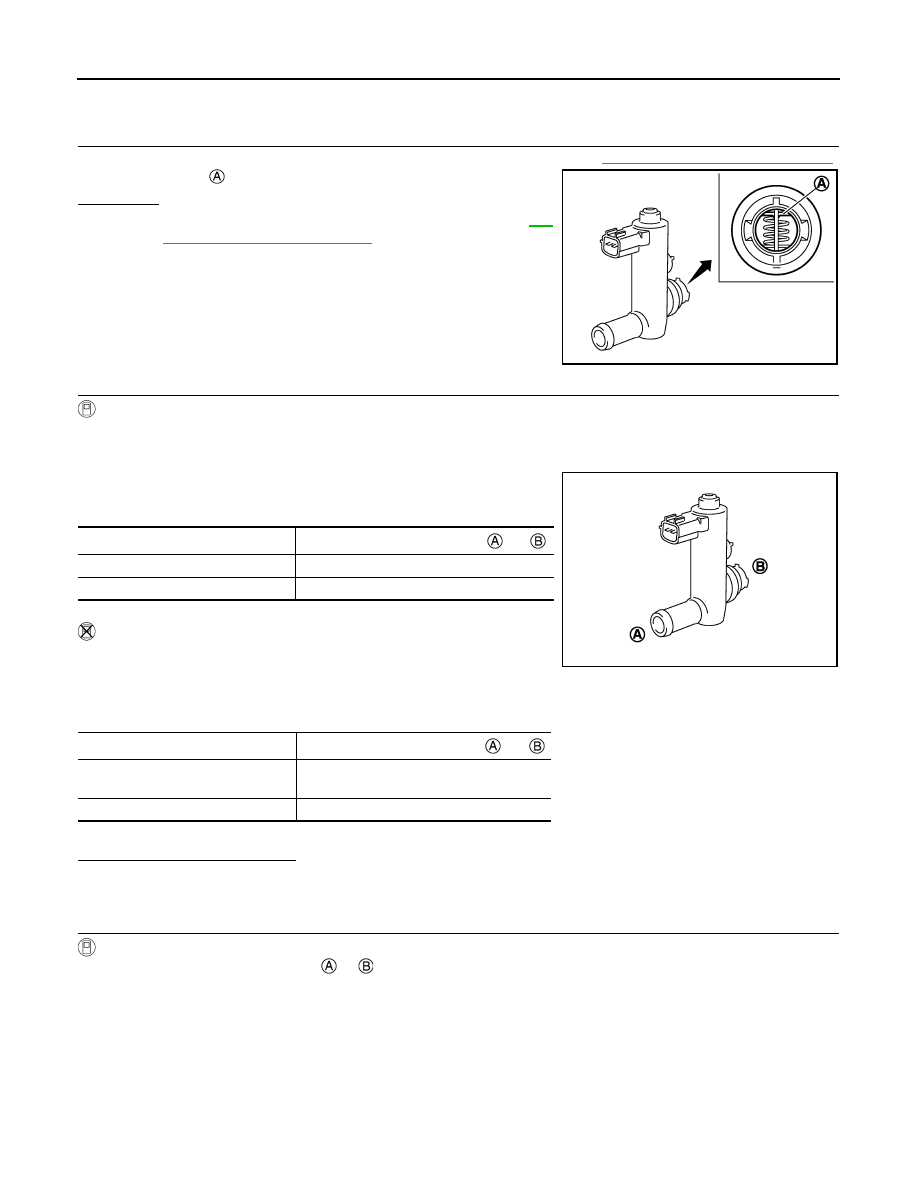
1.

CHECK EVAP CANISTER VENT CONTROL VALVE-I

1. Remove EVAP canister vent control valve from EVAP canister. Refer to 

FL-18, "Removal and Installation"

.

2. Check portion   of EVAP canister vent control valve for rust.
Is it rusted?

YES

>> Replace EVAP canister vent control valve. Refer to 

FL-

18, "Removal and Installation"

.

NO

>> GO TO 2.

2.

CHECK EVAP CANISTER VENT CONTROL VALVE-II

With CONSULT

1. Reconnect harness connectors disconnected.

2. Turn ignition switch ON.

3. Perform “VENT CONTROL/V” in “ACTIVE TEST” mode.

4. Check air passage continuity and operation delay time.

Check that new O-ring is installed properly.

Operation takes less than 1 second.

Without CONSULT

1. Disconnect EVAP canister vent control valve harness connector.

2. Check air passage continuity and operation delay time under the

following conditions.

Check that new O-ring is installed properly.

Operation takes less than 1 second.

Is the inspection result normal?

YES

>> INSPECTION END

NO

>> GO TO 3.

3.

CHECK EVAP CANISTER VENT CONTROL VALVE-III

With CONSULT

1. Clean the air passage [portion   to  ] of EVAP canister vent control valve using an air blower.

2. Perform “VENT CONTROL/V” in “ACTIVE TEST” mode.

JMBIA0168ZZ

Condition VENT CONTROL/V

Air passage continuity between 

 and 

ON

Not existed

OFF

Existed

Condition

Air passage continuity between 

 and 

12 V direct current supply between
 terminals 1 and 2

Not existed

OFF

Existed

JMBIA0169ZZ

P0448 EVAP CANISTER VENT CONTROL VALVE

EC-311

< DTC/CIRCUIT DIAGNOSIS >

[VQ35DE]

C

D

E

F

G

H

I

J

K

L

M

A

EC

N

P

O

3. Check air passage continuity and operation delay time.

Check that new O-ring is installed properly.

Operation takes less than 1 second.

Without CONSULT

1. Clean the air passage [portion   to  ] of EVAP canister vent

control valve using an air blower.

2. Check air passage continuity and operation delay time under the following conditions.

Check that new O-ring is installed properly.

Operation takes less than 1 second.

Is the inspection result normal?

YES

>> INSPECTION END

NO

>> Replace EVAP canister vent control valve. Refer to 

FL-18, "Removal and Installation"

.

Condition VENT CONTROL/V

Air passage continuity between 

 and 

ON

No

OFF

Yes

Condition

Air passage continuity between 

 and 

12 V direct current supply between
 terminals (1) and (2)

No

OFF

Yes

JMBIA0169ZZ

EC-312

< DTC/CIRCUIT DIAGNOSIS >

[VQ35DE]

P0451 EVAP CONTROL SYSTEM PRESSURE SENSOR

P0451 EVAP CONTROL SYSTEM PRESSURE SENSOR

DTC Logic

INFOID:0000000009178218

DTC DETECTION LOGIC

DTC CONFIRMATION PROCEDURE

NOTE:

Never remove fuel filler cap during DTC confirmation procedure.

1.

PRECONDITIONING

If DTC Confirmation Procedure has been previously conducted, always perform the following procedure

before conducting the next test. 

1. Turn ignition switch OFF and wait at least 10 seconds.

2. Turn ignition switch ON.

3. Turn ignition switch OFF and wait at least 10 seconds.

With CONSULT>>GO TO 2.
Without CONSULT>>GO TO 5.

2.

PERFORM DTC CONFIRMATION PROCEDURE-1

With CONSULT

1. Start engine and let it idle for least 40 seconds.

NOTE:

Do not depress accelerator pedal even slightly.

2. Check 1st trip DTC.
Is 1st trip DTC detected?

YES

>> Proceed to 

EC-314, "Diagnosis Procedure"

.

NO

>> GO TO 3.

3.

PERFORM DTC CONFIRMATION PROCEDURE-2

With CONSULT

1. Select “EVAP DIAG READY” in “DATA MONITOR” mode of “ENGINE”.

2. Let it idle until “OFF” of “EVAP DIAG READY” changes to “ON”.

NOTE:

It will take at most 2 hours until “OFF” of “EVAP DIAG READY” changes to “ON”.

3. Turn ignition switch OFF and wait at least 90 minutes.

NOTE:

Never turn ignition switch ON during 90 minutes.

4. Turn ignition switch ON.

5. Select “EVAP LEAK DIAG” in “DATA MONITOR” mode of “ENGINE”.

6. Check that “EVAP LEAK DIAG” indication.

DTC No.

CONSULT screen terms

(Trouble diagnosis content)

DTC detecting condition

Possible cause

P0451

EVAP SYS PRES SEN
(Evaporative emission sys-
tem pressure sensor/switch 
range/performance)

ECM detects a sloshing signal from the 
EVAP control system pressure sensor

• Harness or connectors

(EVAP control system pressure sensor 
circuit is shorted.)
[CKP sensor (POS) circuit is shorted.]
(APP sensor 2 circuit is shorted.)
(Refrigerant pressure sensor circuit is 
shorted.)
(Engine oil pressure sensor circuit is 
shorted.)

• EVAP control system pressure sensor
• Crankshaft position sensor (POS)
• Accelerator pedal position sensor
• Refrigerant pressure sensor
• Engine oil pressure sensor
• Sensor power supply 2 circuit

P0451 EVAP CONTROL SYSTEM PRESSURE SENSOR

EC-313

< DTC/CIRCUIT DIAGNOSIS >

[VQ35DE]

C

D

E

F

G

H

I

J

K

L

M

A

EC

N

P

O

Which is displayed on CONSULT?

CMPLT >> GO TO 4.

YET

>> 1. Perform DTC CONFIRMATION PROCEDURE again.

2. GO TO 1.

4.

PERFORM DTC CONFIRMATION PROCEDURE-3

With CONSULT

Check 1st trip DTC.
Is 1st trip DTC detected?

YES

>> Proceed to 

EC-314, "Diagnosis Procedure"

.

NO

>> INSPECTION END

5.

PERFORM DTC CONFIRMATION PROCEDURE-4

With GST

1. Start engine and let it idle for least 40 seconds.

NOTE:

Do not depress accelerator pedal even slightly.

2. Check 1st trip DTC.
Is 1st trip DTC detected?

YES

>> Proceed to 

EC-314, "Diagnosis Procedure"

.

NO

>> GO TO 6.

6.

PERFORM DTC CONFIRMATION PROCEDURE-5

With GST

1. Let it idle for at least 2 hours.

2. Turn ignition switch OFF and wait at least 90 minutes.

NOTE:

Never turn ignition switch ON during 90 minutes.

3. Turn ignition switch ON.

4. Check 1st trip DTC.
Is 1st trip DTC detected?

YES

>> Proceed to 

EC-314, "Diagnosis Procedure"

.

NO

>> INSPECTION END

Diagnosis Procedure

INFOID:0000000009178219

1.

CHECK EVAP CONTROL SYSTEM PRESSURE SENSOR CONNECTOR FOR WATER

1. Disconnect EVAP control system pressure sensor harness connector.

2. Check that water is not inside connectors.
Is the inspection result normal?

YES

>> GO TO 2.

NO

>> Repair or replace error-detected parts.

2.

CHECK EVAP CONTROL SYSTEM PRESSURE SENSOR POWER SUPPLY

1. Turn ignition switch ON.

2. Check the voltage between EVAP control system pressure sensor harness connector and ground.

Is the inspection result normal?

YES

>> GO TO 4.

NO

>> GO TO 3.

3.

CHECK SENSOR POWER SUPPLY 2 CIRCUIT

Check sensor power supply 2 circuit. Refer to 

EC-450, "Diagnosis Procedure"

.

EVAP control system pressure sensor

Ground

Voltage (V)

Connector

Terminal

B36

3

Ground

Approx. 5


Content   ..  499  500  501  502   ..