Nissan Pathfinder. Instruction - part 392
DLN-10
< SYSTEM DESCRIPTION >
[TRANSFER: TY21C]
COMPONENT PARTS
SYSTEM DESCRIPTION
COMPONENT PARTS
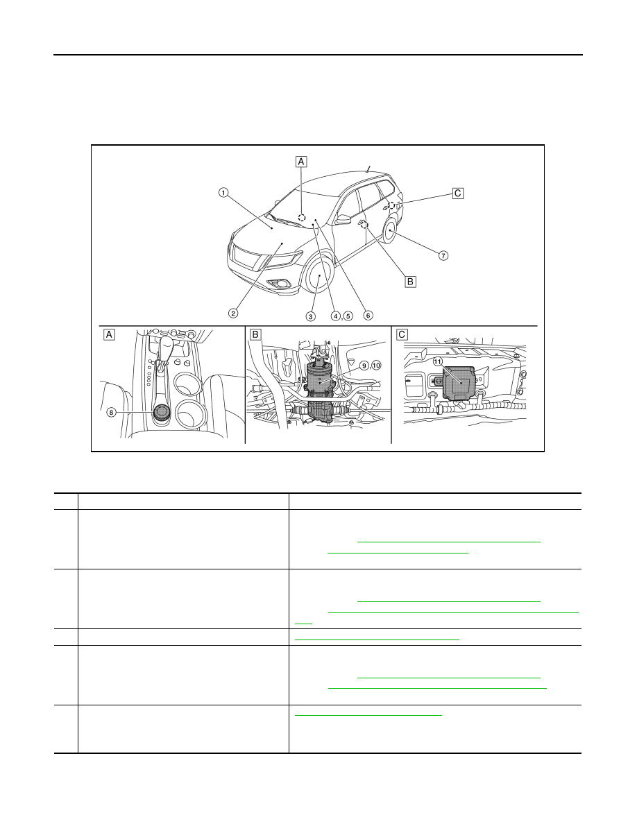
Component Parts Location
INFOID:0000000009177706
A.
Center console area
B.
Rear final drive assembly
C.
Inside storage room
No.
Component parts
Reference/Function
1
ABS actuator and electric unit (control unit)
Transmits/receives the signals for control of 4WD system via CAN com-
munication line to/from 4WD control unit. For transmitting/receiving mainly
signals, refer to
DLN-15, "4WD SYSTEM : System Description"
BRC-7, "Component Parts Location"
for detailed installation loca-
tion.
2
ECM
Transmits/receives the signals for control of 4WD system via CAN com-
munication line to/from 4WD control unit. For transmitting/receiving mainly
signals, refer to
DLN-15, "4WD SYSTEM : System Description"
Refer to
EC-14, "ENGINE CONTROL SYSTEM : Component Parts Loca-
for detailed installation location.
3
Front wheel sensor
BRC-9, "Wheel Sensor and Sensor Rotor"
4
Combination meter
Transmits/receives the signals for control of 4WD system via CAN com-
munication line to/from 4WD control unit. For transmitting/receiving mainly
signals, refer to
DLN-15, "4WD SYSTEM : System Description"
MWI-6, "METER SYSTEM : Component Parts Location"
for de-
tailed installation location.
5
Vehicle information display
DLN-11, "Vehicle Information Display"
• 4WD mode indicator
• Torque distribution indicator
• 4WD warning indicator
ALDIA0374ZZ