Nissan Pathfinder. Instruction - part 365
DLK-226
< DTC/CIRCUIT DIAGNOSIS >
HOOD SWITCH
HOOD SWITCH
Component Function Check
INFOID:0000000009175788
1.
CHECK FUNCTION
1. Select HOOD SW in Data Monitor mode of IPDM E/R using CONSULT.
2. Check HOOD SW indication under the following condition.
Is the indication normal?
YES
>> Hood switch is OK.
NO
>> Go to
DLK-226, "Diagnosis Procedure"
.
Diagnosis Procedure
INFOID:0000000009175789
Regarding Wiring Diagram information, refer to
.
1.
CHECK HOOD SWITCH SIGNAL CIRCUITS
1. Turn ignition switch OFF.
2. Disconnect hood switch connector.
3. Check voltage between hood switch harness connector and ground.
Is the inspection result normal?
YES
>> GO TO 3.
NO
>> GO TO 2.
2.
CHECK HOOD SWITCH SIGNAL CIRCUITS
1. Disconnect IPDM E/R connector.
2. Check continuity between IPDM E/R harness connector and hood switch harness connector.
3. Check continuity between IPDM E/R harness connector and ground.
Is the inspection result normal?
YES
>> Replace IPDM E/R. Refer to
PCS-32, "Removal and Installation"
NO
>> Repair or replace harness.
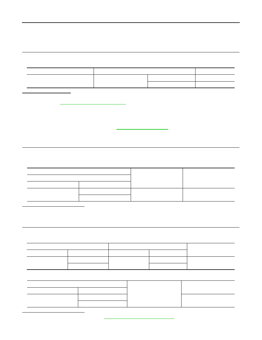
Monitor item
Condition
Indication
HOOD SW
Hood
Open
ON
Close
OFF
(+)
(–)
Voltage (V)
(Approx.)
Hood switch
Connector
Terminal
E205
1
Ground
12
2
IPDM E/R
Hood switch
Continuity
Connector
Terminal
Connector
Terminal
E218
94
E205
1
Yes
96
2
IPDM E/R
Ground
Continuity
Connector
Terminal
E218
94
No
96