Nissan Pathfinder. Instruction - part 344
DLK-142
< DTC/CIRCUIT DIAGNOSIS >
B2427 ENCODER
Is the inspection result normal?
YES
>> GO TO 4.
NO
>> Replace automatic back door control module. Refer to
DLK-321, "Removal and Installation"
.
4.
CHECK ENCODER POWER SUPPLY
1. Turn ignition switch OFF.
2. Disconnect spindle unit RH connector.
3. Check voltage between spindle unit RH harness connector and ground.
Is the inspection result normal?
YES
>> GO TO 6.
NO
>> GO TO 5.
5.
CHECK ENCODER CIRCUIT
1. Disconnect automatic back door control module connector.
2. Check continuity between automatic back door control module harness connector and spindle unit RH
harness connector.
3. Check continuity between automatic back door control module harness connector and ground.
Is the inspection result normal?
YES
>> Replace automatic back door control module. Refer to
DLK-321, "Removal and Installation"
.
NO
>> Repair or replace harness.
6.
CHECK ENCODER CIRCUIT 2
1. Disconnect automatic back door control module connector.
2. Check continuity between automatic back door control module harness connector and spindle unit RH
harness connector.
3. Check continuity between automatic back door control module harness connector and ground.
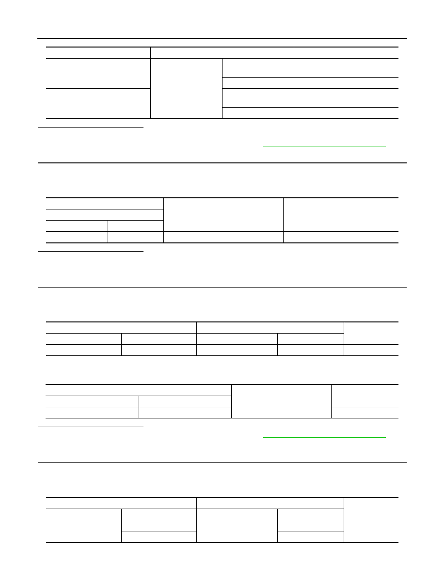
Monitor item
Condition
Status
SPINDLE RH ENCODER A
Back door
Moving (auto or manu-
al)
HI
⇔ LO
When stopped
HI or LO
SPINDLE RH ENCODER B
Moving (auto or manu-
al)
HI
⇔ LO
When stopped
HI or LO
(+)
(–)
Voltage
(Approx.)
Spindle unit RH
Connector
Terminal
B162
8
Ground
Battery voltage
Automatic back door control module
Spindle unit RH
Continuity
Connector
Terminal
Connector
Terminal
B55
20
B162
8
Yes
Automatic back door control module
Ground
Continuity
Connector
Terminal
B55
20
No
Automatic back door control module
Spindle unit RH
Continuity
Connector
Terminal
Connector
Terminal
B55
8
B162
3
Yes
9
10