Nissan Pathfinder. Instruction - part 339
DLK-122
< DTC/CIRCUIT DIAGNOSIS >
B2416 TOUCH SENSOR RH
Is the inspection result normal?
YES
>> GO TO 5.
NO
>> GO TO 4.
4.
CHECK TOUCH SENSOR RH CIRCUIT
1. Disconnect automatic back door control module and touch sensor RH connector.
2. Check continuity between automatic back door control module harness connector and touch sensor RH
harness connector.
3. Check continuity between automatic back door control module harness connector and ground.
Is the inspection result normal?
YES
>> Replace automatic back door control module. Refer to
DLK-321, "Removal and Installation"
.
NO
>> Repair or replace harness.
5.
CHECK TOUCH SENSOR RH GROUND CIRCUIT
1. Disconnect automatic back door control module and touch sensor RH connector.
2. Check continuity between automatic back door control module harness connector and touch sensor RH
harness connector.
3. Check continuity between automatic back door control module harness connector and ground.
Is the inspection result normal?
YES
>> GO TO 6.
NO
>> Repair or replace harness.
6.
CHECK TOUCH SENSOR RH GROUND CIRCUIT 2
1. Connect automatic back door control module and touch sensor RH connector.
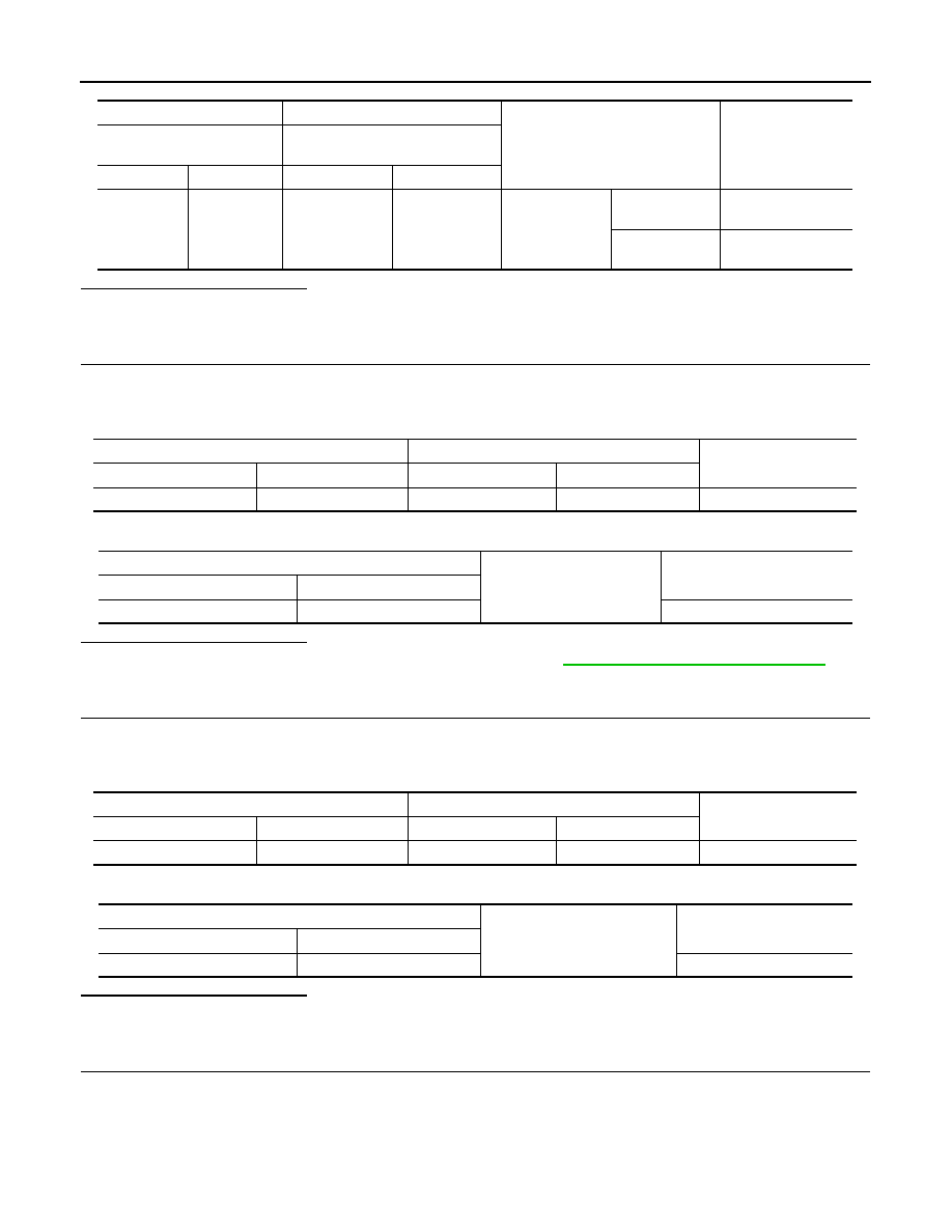
2. Check voltage between automatic back door control module harness connector and ground.
(+)
(–)
Condition
Voltage
(Approx.)
Touch sensor RH
Automatic back door control mod-
ule
Connector
Terminal
Connector
Terminal
D555
1
B55
13
Touch sensor
RH
Detect obstruc-
tion
1.8 – 5 V
Other than
above
2.72 – 7.27 V
Automatic back door control module
Touch sensor RH
Continuity
Connector
Terminal
Connector
Terminal
B55
1
D555
1
Yes
Automatic back door control module
Ground
Continuity
Connector
Terminal
B55
1
No
Automatic back door control module
Touch sensor RH
Continuity
Connector
Terminal
Connector
Terminal
B55
13
D555
2
Yes
Automatic back door control module
Ground
Continuity
Connector
Terminal
B55
13
No