Content .. 1217 1218 1219 1220 ..
Nissan Pathfinder. Instruction - part 1219
WT-58
< PERIODIC MAINTENANCE >
WHEEL AND TIRE ASSEMBLY
WHEEL AND TIRE ASSEMBLY
Adjustment
INFOID:0000000009177462
BALANCING WHEELS (ADHESIVE WEIGHT TYPE)
Preparation Before Adjustment
Remove inner and outer balance weights from the road wheel. Using releasing agent, remove double-faced
adhesive tape from the road wheel.
CAUTION:
• Be careful not to scratch the road wheel during removal.
• After removing double-faced adhesive tape, wipe clean all traces of releasing agent from the road
wheel.
Wheel Balance Adjustment
CAUTION:
• DO NOT use center hole cone-type clamping machines to hold the wheel assembly during tire
removal/installation or balancing or damage to the wheel paint, cladding or chrome may result. Use
only rim-type or universal lug-type clamping machines to hold the wheel assembly during servicing.
• If a balancer machine has an adhesive weight mode setting, select the adhesive weight mode setting and
skip Step 2 below. If a balancer machine only has the clip-on (rim flange) weight mode setting, follow Step 2
to calculate the correct size adhesive weight.
1. Set road wheel on balancer machine using the center hole as a guide. Start the balancer machine.
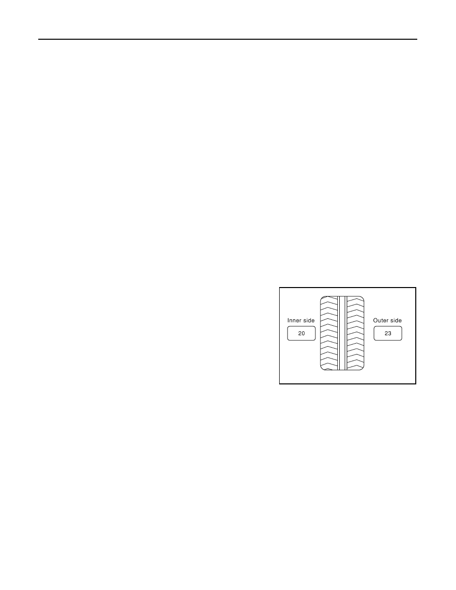
2. For balancer machines that only have a clip-on (rim flange) weight mode setting, follow this step to calcu-
late the correct size adhesive weight to use. When inner and outer imbalance values are shown on the
balancer machine indicator, multiply outer imbalance value by 5/3 (1.67) to determine balance weight that
should be used. Select the outer balance weight with a value closest to the calculated value above and
install in to the designated outer position of or at the designated angle in relation to the road wheel.
a. Indicated imbalance value
× 5/3 (1.67) = balance weight to be
installed
Calculation example:
23 g (0.81 oz)
× 5/3 (1.67) = 38.33 g (1.35 oz) ⇒ 40 g (1.41 oz)
balance weight (closer to calculated balance weight value)
NOTE:
Note that balance weight value must be closer to the calculated
balance weight value.
Example:
37.4
⇒ 35 g (1.23 oz)
37.5
⇒ 40 g (1.41 oz)
SMA054D